This lab continues the series demonstrating how an AS can use Local Preference to control outbound routing paths, and how to use MEDs (multi-exit discriminators or metrics), BGP communities, AS path prepends, and subnet leaking to determine inbound routing paths. All five are very powerful tools for ISPs to control how their external peering links are used.
Refer to the BGP presentations and documentation for more information about the BGP path selection process and the default values for, and priorities of, the “local_pref” and “metric” attributes.
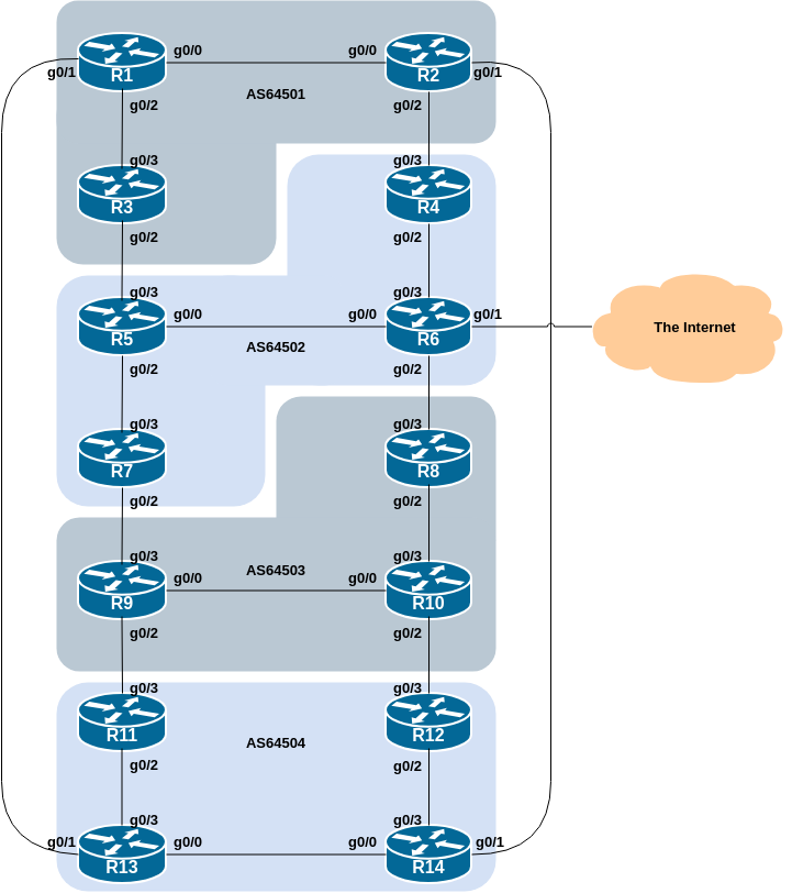
The following common topology is used for this lab.
As a reminder, the diagram below displays the desired traffic flows between particular routers and ASes. Eight traffic flows are to be implemented.
The arrows in the diagram show the flows that will be configured. Each arrow originates from a border router in an AS, and terminates on one of the routers in another AS. This signifies the traffic flows desired for the links between the two routers.
Each of the policy labs we are going to do has a description on how to implement the traffic flow represented by each arrow. It is important to pause and think what the policy is, and what needs to be done to achieve it.
If at any time there is any doubt as to the configuration required, ask the lab instructors.
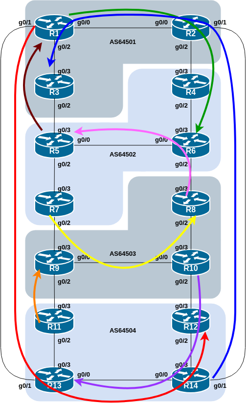
The diagram may look “busy” but the key to success is to focus on the traffic engineering that your group needs to do, and “ignore” the other activities by other groups.
As a reminder, the addressing used for this lab is documented in the address plan and is replicated here for convenience:
| AS Number | Router | IPv4 subnet | IPv6 subnet |
|---|---|---|---|
| AS64501 | Router1 | 100.68.1.32/28 | 2001:DB8:1:100::/56 |
| Router2 | 100.68.1.48/28 | 2001:DB8:1:200::/56 | |
| Router3 | 100.68.1.64/28 | 2001:DB8:1:300::/56 | |
| AS64502 | Router4 | 100.68.2.32/28 | 2001:DB8:2:100::/56 |
| Router5 | 100.68.2.48/28 | 2001:DB8:2:200::/56 | |
| Router6 | 100.68.2.64/28 | 2001:DB8:2:300::/56 | |
| Router7 | 100.68.2.80/28 | 2001:DB8:2:400::/56 | |
| AS64503 | Router8 | 100.68.3.32/28 | 2001:DB8:3:100::/56 |
| Router9 | 100.68.3.48/28 | 2001:DB8:3:200::/56 | |
| Router10 | 100.68.3.64/28 | 2001:DB8:3:300::/56 | |
| AS64504 | Router11 | 100.68.4.32/28 | 2001:DB8:4:100::/56 |
| Router12 | 100.68.4.48/28 | 2001:DB8:4:200::/56 | |
| Router13 | 100.68.4.64/28 | 2001:DB8:4:300::/56 | |
| Router14 | 100.68.4.80/28 | 2001:DB8:4:400::56 |
Before we start with this scenario it is important that the configuration from the MED lab is removed.
This involves removing the route-maps, prefix-lists and the per-neighbour configuration to set MED.
All router teams should do this, and then do a route-refresh of their EBGP peerings.
This lab in the BGP Policy series introduces the second of four methods of influencing inbound policies, the BGP Community.
Here Communities are used to demonstrate how to influence inbound traffic flows. BGP Communities have replaced MEDs for policy configuration such as this, with many network operators now supporting peers and customers using pre-defined MEDs to influence traffic paths.
Rather than using MEDs as we did in the previous scenario, we will signal to our neighbouring ASN by using BGP communities. To prepare for this we need to establish which communities will implement the policies replacing the MEDs. Setting low MED means that the path would be preferred over one with high MED. This could be replicated in the peer AS by that AS setting high local preference on the path that would have heard the low MED, and by setting low local preference on the path that would have heard the high MED.
As a recommendation, configure community
<localASN>:150 to set high priority for outbound
traffic, and <localASN>:50 to set low priority for
outbound traffic. This means that each AS will have to configure a
community matching route-map to set the appropriate
local-preference value. Here is a sample configuration:
ip community-list standard HIGH-pref permit 6450X:150
ip community-list standard LOW-pref permit 6450X:50
where each group should replace X with their Group number.
Next we create a route-map which will set
local-preference for each of the communities. If the EBGP
neighbour sends us the community attached to a prefix, we
will apply local-preference to the prefix depending on the
community value attached.
Here is a sample configuration:
route-map customer-comm permit 10
 match community HIGH-pref
 set local-preference 150
!
route-map customer-comm permit 20
 match community LOW-pref
 set local-preference 50
!
route-map customer-comm permit 30
!
With the route-map configured, we now apply it to all
our EBGP neighbours. When they send prefixes with the appropriate
communities set, we will now set the local preference.
Here is a sample configuration:
router bgp 6450X
 address-family ipv4
  neighbor <ebgp-peer> remote-as 6450Y
  neighbor <ebgp-peer> route-map customer-comm in
!
 address-family ipv6
  neighbor <ebgp-peer> remote-as 6450Y
  neighbor <ebgp-peer> route-map customer-comm in
!
Replace X with your Group number, and Y with the your neighbouring Group number.
Note that the same route-map can be used for both IPv4
and IPv6 peerings! This is because the route-map has no IP
address family specific configuration in it - it is matching against a
BGP attribute rather than the address prefix itself.
While the whole concept looks more complex at first glance, it actually scales a lot better as the service provider is able to standardise their policy configuration using communities all across their access network.
Now that we have prepared the community matching policy configuration, we can implement the policies to influence inbound traffic flows.
As for the previous scenario, please read the instructions carefully, and discuss within your team, and in your AS, how you are going to implement the following.
The example in this step achieves exactly the same traffic flow between neighbouring ASes as in the previous scenario for the networks in question. Refer to the diagram above for a picture of the traffic flow…
AS 64501:
All traffic TO 100.68.1.32/28 and 2001:DB8:1:100::/56 (Router1) from anywhere in AS 64502 must enter AS 64501 via the Router5 – Router3 link. (Hint: this means that Router2 must announce 100.68.1.32/28 and 2001:DB8:1:100::/56 to AS 64502 with AS 64502’s low priority community whereas the equivalent announcement from Router3 needs AS 64502’s high priority community.)
All traffic TO 100.68.1.64/28 and 2001:DB8:1:300::/56 (Router3) from anywhere in AS 64504 must enter AS 64501 via the Router14 – Router2 link. (Hint: this means that Router1 must announce 100.68.1.64/28 and 2001:DB8:1:300::/56 to AS 64504 with AS 64504’s low priority community whereas the equivalent announcement from Router2 needs AS 64504’s high priority community.)
AS 64502:
All traffic TO 100.68.2.48/28 and 2001:DB8:2:200::/56 (Router5) from anywhere in AS 64503 must enter AS 64502 via the Router8 – Router6 link. (Hint: this means that Router7 must announce 100.68.2.48/28 and 2001:DB8:2:200::/56 to AS 64503 with AS 64503’s low priority community whereas the equivalent announcement from Router6 needs AS 64503’s high priority community.)
All traffic TO 100.68.2.64/28 and 2001:DB8:2:300::/56 (Router6) from anywhere in AS 64501 must enter AS 64502 via the Router2 – Router4 link. (Hint: this means that Router5 must announce 100.68.2.64/28 and 2001:DB8:2:300::/56 to AS 64501 with AS 64501’s low priority community whereas the equivalent announcement from Router4 needs AS 64501’s high priority community.)
AS 64503:
All traffic TO 100.68.3.32/28 and 2001:DB8:3:100::/56 (Router8) from anywhere in AS 64502 must enter AS 64503 via the Router7 – Router9 link. (Hint: this means that Router8 must announce 100.68.3.32/28 and 2001:DB8:3:100::/56 to AS 64502 with AS 64502’s low priority community whereas the equivalent announcement from Router9 needs AS 64502’s high priority community.)
All traffic TO 100.68.3.48/28 and 2001:DB8:3:200::/56 (Router9) from anywhere in AS 64504 must enter AS 64503 via the Router11 – Router9 link. (Hint: this means that Router10 must announce 100.68.3.48/28 and 2001:DB8:3:200::/56 to AS 64504 with AS 64504’s low priority community whereas the equivalent announcement from Router9 needs AS 64504’s high priority community.)
AS 64504:
All traffic TO 100.68.4.48/28 and 2001:DB8:4:200::/56 (Router12) from anywhere in AS 64501 must enter AS 64504 via the Router1 – Router13 link. (Hint: this means that Router14 must announce 100.68.4.48/28 and 2001:DB8:4:200::/56 to AS 64501 with AS 64501’s low priority community whereas the equivalent announcement from Router13 needs AS 64501’s high priority community.)
All traffic TO 100.68.4.64/28 and 2001:DB8:4:300::/56 (Router13) from anywhere in AS 64503 must enter AS 64504 via the Router10 – Router12 link. (Hint: this means that Router11 must announce 100.68.4.64/28 and 2001:DB8:4:300::/56 to AS 64503 with AS 64503’s low priority community whereas the equivalent announcement from Router12 needs AS 64503’s high priority community.)
The traffic flow we want to achieve above is also visually described in the earlier lab diagram, where the coloured arrows show the traffic flow we want to achieve between ASes.
The following configuration snippet shows what could be done for Router8 (showing the IPv4 and IPv6 policy statements) in its peering with Router6 in the AS64503 example above:
ip prefix-list R8-v4prefix permit 100.68.3.32/28
!
ipv6 prefix-list R8-v6prefix permit 2001:DB8:3:100::/56
!
route-map R6-v4comm permit 10
 match ip address prefix-list R8-v4prefix
 set community 64502:50
!
route-map R6-v4comm permit 20
!
route-map R6-v6comm permit 10
 match ip address prefix-list R8-v6prefix
 set community 64502:50
!
route-map R6-v6comm permit 20
!
router bgp 64503
 address-family ipv4
  neighbor 100.68.2.8 remote-as 64502
  neighbor 100.68.2.8 route-map R6-v4comm out
  neighbor 100.68.2.8 route-map customer-comm in
!
 address-family ipv6
  neighbor 2001:DB8:2:5::1 remote-as 64502
  neighbor 2001:DB8:2:5::1 route-map R6-v6comm out
  neighbor 2001:DB8:2:5::1 route-map customer-comm in
!
Notice again the use of descriptive names for the prefix-lists and route-maps.
Use the above example to come up with a configuration for your router and the policy it needs to implement on its EBGP session. Discuss with the other members of your group (your AS) - it is likely that you will have some common configuration snippets you can share with each other.
Note: Router2 and Router9 have two EBGP peers, and will need a separate route-map for each peering. Use the hint above, naming the route-map after the peer name (and is also common practice in day to day network operations).
Once the policy has been implemented, remember to run a route-refresh
on the EBGP session. And then try doing a traceroute (trace
command, and remember to specify the source interface – why?) through
the network, to the destination you have targeted. Does the traceroute
follow the arrows in the diagram? If not, why not? Maybe check the BGP
table and if your colleagues in your AS have completed their steps in
the exercise as well.
On completion of the exercise the instructor will display traceroutes to the selected destinations on the classroom screen - the traffic has to enter the AS as specified in the exercise above and the instructor will check from various points of the lab that the traffic is flowing as intended.