This lab continues from the previous one by adding IS-IS to the configured, addressed and confirmed working interfaces. Please refer to the Setup Lab for further information.
The pre-requisites for this lab is that the Setup lab has been completed and the instructors have presented the Introduction to IS-IS presentation.
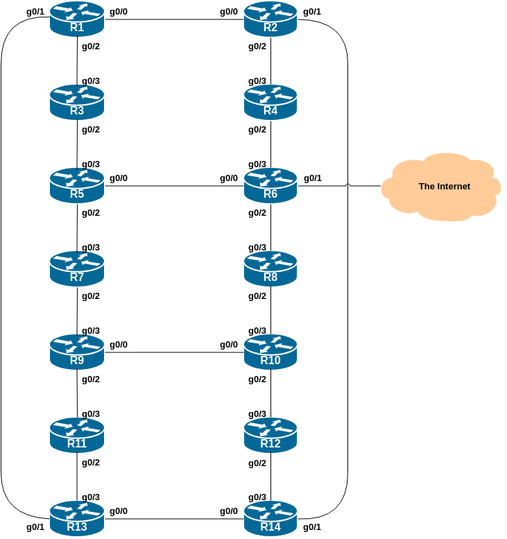
The following common topology is used for the first series of labs.
After reviewing the IS-IS presentation just presented, each router
team will now enable IS-IS on their router. We will use
workshop as the IS-IS ID in the configuration.
For this lab, we use level-2 in one area (49.0001) and use wide metrics (IOS default is the historical narrow metric and is not considered good practice due to the limited scope available).
The following sections will step through the details of configuring IS-IS.
Recall from the IS-IS presentation that there were two suggested ways of configuring an NET address. We will use the simpler method here1, the convention used for IPv6 deployments, where the format used is 49.0001.pop#.router#.00. For this lab our point of presence number is zero as we only have one PoP.
For example, the loopback for Router1 is 2001:DB8:0:FFFF::1 which will make the NSAP address 49.0001.0000.0001.00 (remember that the shortest length for an NSAP address is 64 bits, so this is the shortest value we can use). Or, for Router14 loopback of 2001:DB8:0:FFFF::E, making the NSAP address 49.0001.0000.000E.00.
Here is the template to use: replace the X with the last character of the IPv6 Loopback address:
router isis workshop
 net 49.0001.0000.000X.00
!
IS-IS on Cisco IOS defaults to having each IS existing
inlevel-1 and level-2 at the same time. As we
learned in the presentation, this is unnecessary/wasteful, and so we
need to change the default to level-2-only, which has been
the industry best practice for many years.
router isis workshop
 is-type level-2-only
!
We also set the metric-style to wide. IS-IS supports two
types of metric, narrow (historic now and not suitable for
modern networks) and wide. IOS still defaults to
narrow metrics, so we need to enter explicit configuration
to change this to wide.
This configuration below sets the metric style to be
wide:
router isis workshop
 metric-style wide
!
As we will be running a dual stack network, we need to activate
multi-topology. As was covered in the presentation, this
creates a separate IPv4 and IPv6 topology database within the IS-IS
process, meaning that the network can support routers that may only run
single protocol (either only IPv4, or only IPv6), and we can
incrementally deploy IPv6 if we wish:
router isis workshop
 address-family ipv6
  multi-topology
!
The default metric in IS-IS is 10 on all interfaces irrespective of their physical bandwidth. It is considered best practice these days to change the default metric from 10 to a very high value, for example 100000, so that network outages will not be caused by misconfiguration of newly introduced routers, or misconfigured interfaces which could accidentally and unintentionally take full traffic load.
We now set the default metric for both IPv4 and IPv6 topologies to be 100000:
router isis workshop
 metric 100000
!
 address-family ipv6
  metric 100000
!
As we will be using neighbour authentication as discussed in the
IS-IS presentation, first we create the authentication key-chain. We are
using isplab as the key here.
key chain isis-key
 key 1
  key-string isplab
!
The authentication is added in to the IS-IS process, meaning that authentication will be applied to every interface enabled for IS-IS.
router isis workshop
 authentication mode md5 level-2
 authentication key-chain isis-key level-2
!
Neighbouring routers that do not have the same key configured will not be able to exchange LSPs. The CLNS status will indicate an adjacency, but IS-IS will not work. And you will see log messages similar to:
%CLNS-4-AUTH_FAIL: ISIS: LAN IIH authentication failed
%CLNS-4-AUTH_FAIL: ISIS: LSP authentication failed
%CLNS-4-AUTH_FAIL: ISIS: PSNP authentication failed
for any adjacency authentication failure.
It is helpful to have IS-IS notify of adjacency changes, and these are sent to the router’s logging system, and can be sent to the operator’s log collecting system (when configured). To turn on IS-IS adjacency logging, we do:
router isis workshop
 log-adjacency-changes
!
To see any log messages on the router, use the command
show logging - in the setup lab we added detailed
timestamps to all the log messages and so the IS-IS logs will also
appear with those.
When a router restarts after being taken out of service, IS-IS will start distribute prefixes as soon as adjacencies are established with its neighbours. In the next part of the workshop lab, we will be introducing IBGP. So if a router restarts, IS-IS will start up well before the IBGP mesh is re-established. This will result in the router landing in the transit path for traffic, with out the routing table being completed by BGP. There will not be complete routing information on the router, so any transit traffic (from customer to peer or upstream, or vice-versa) will be either dropped, or resulting in packets bouncing back and forth between adjacent routers. To avoid this problem, we require the router to not announce it is availability until the IBGP mesh is up and running. To do this, we have to provide the following command:
router isis workshop
 set-overload-bit on-startup wait-for-bgp
!
 address-family ipv6
  set-overload-bit on-startup wait-for-bgp
!
This sets IS-IS’ overload2 bit such that all routes via this router will be marked as unreachable (very high metric) until IBGP is up and running. Once IBGP is running, the prefixes distributed by IS-IS will revert to standard metric values, and the router will pass transit traffic as normal.
Now that the IS-IS process is fully configured, we can turn our attention to the physical interfaces that will be activated for IS-IS.
We now set the IS-IS metric on each physical interface (needs to be done for both IPv4 and IPv6) - we don’t want to rely on just the router’s default metric we set earlier, as we may have traffic engineering needs within our network.
The default IS-IS metric for all interface types is 10. Unlike OSPF
in Cisco IOS, IS-IS has no automatic scheme to convert the interface
bandwidth into a metric value. ISPs deploying IS-IS have to come up with
their own scheme (as in fact many ISPs using OSPF now also do). In the
lab we will use metric 2 for the Ethernet interfaces.
Here is an example configuration setting the IS-IS metric for IPv4
and IPv6 on an interface GigabitEthernet0/0:
interface GigabitEthernet0/0
 isis metric 2
 isis ipv6 metric 2
!
Each router team should now go to each active interface on their router and set the IS-IS metric on them. Only do this for active interfaces - each router has 4 interfaces, but only a subset of those are in use - consult the network diagram if you are unsure which.
All connected interfaces can now to be enabled within IS-IS.
Note that IS-IS considers an ethernet interface as a broadcast
interface by default, so will normally proceed with a DIS election once
enabled and the first neighbour is found. We are using ethernet as a
point-to-point link here, so we need to notify this in the
configuration.
Here is an example configuration activating IS-IS on a point-to-point
interface GigabitEthernet0/0:
interface GigabitEthernet0/0
 isis network point-to-point
 ip router isis workshop
 ipv6 router isis workshop
!Note: the IS-IS ID on the interfaces must match the router’s IS-IS ID. Spelling mistakes will result in a new IS-IS process being created on the router (it can support multiple).
Each router team should now go to back to each active interface on their router and enable IS-IS on them.
Remember the Interface Rules on Cisco IOS (from the presentation):
ip[v6] router isis on an interface means that CLNS
adjacencies are sought and the IP subnet used on the interface is
inserted into IS-IS.
passive interface in the IS-IS process for an
interface on the router means that no CLNS adjacencies are sought, but
the IP subnet used is inserted into IS-IS.
No IS-IS configuration for the interface means that no CLNS adjacencies are sought, and no IP subnet used on the interface is put into IS-IS.
Finally we need to announce the Loopback addresses (IPv4 and IPv6) in IS-IS. (On some versions of Cisco IOS we cannot do this until we have at least one interface active for IS-IS on the router.)
We do not need to set up IS-IS adjacencies on the loopback interface as there are no neighbours there, so we mark it as passive:
router isis workshop
 passive-interface Loopback0
!
Note that this will tell IS-IS to install the loopback interface
addresses (IPv4 and IPv6) in the IS-IS RIB. We do NOT
need to add an ip router isis statement onto the loopback
interface itself. This is different from the required OSPF
configuration, and often catches many network engineers and operators
out, especially those who are learning IS-IS after gaining experience
with OSPF on the Cisco platform.
Router6 has the transit link to the outside world. So that other routers in the lab can also access the outside world, Router6 team now has to distribute this default route to the rest of our AS and to the rest of the lab.
To distribute to the other routers in the lab, Router6 needs to configure the following in their IS-IS set up:
router isis workshop
 default-information originate
!
 address-family ipv6
  default-information originate
!
Once the configuration has been added, all other routers in the lab should have a default route for both IPv4 and IPv6, pointing to Router6.
Important Note: this configuration will unconditionally originate the default route from Router6. This is usually sufficient for simple cases where there is one exit from a network to the transit provider. In more complex cases (as we’ll see later), it is preferred to make conditional announcements of the default (if the default exists in the Global RIB, then announce in IS-IS as well) route so that we don’t end up black holing traffic on the router announcing the default if its default path has gone away.
Once IS-IS is working on your router, check with your neighbours if IS-IS is working too. Then check that you can reach all other routers the network.
Easiest way to test this it to ping the IPv4 and IPv6 loopback addresses for each router. Does it all work? If not, what could be wrong? And ask the instructors if you need assistance…
If there are problems, use the following commands to help determine the cause:
| Command | Action |
|---|---|
show clns neighbor |
see a list of CLNS-IS neighbors that the router sees |
show clns interface |
see if IS-IS is configured and see the IS type |
show isis database |
see IS-IS link state database that the router has learned |
show isis topology |
see the IPv4 IS-IS topology as learned by the router |
show isis ipv6 topology |
see the IPv6 IS-IS topology as learned by the router |
show isis rib |
see the IPv4 IS-IS routes that the router has learned |
show isis ipv6 rib |
see the IPv6 IS-IS routes that the router has learned |
show ip route |
see if there is an IPv4 route for the intended destination |
show ipv6 route |
see if there is an IPv6 route for the intended destination |
Once you can ping all the routers, try tracing routes to all the
routers using the trace x.x.x.x command. For example, this
is how we’d trace to Router12:
trace 100.68.15.252If the traceroute times out each hop due to unreachable
destinations, it is possible to interrupt the traceroute
using CTRL-C as the break sequence.
Also try the traceroute using IPv6. This is how we’d
trace the path to Router11:
trace 2001:DB8:0:FFFF::B
Question: Why do some trace paths show multiple IP addresses per hop? Here is an example tracing from Router2 to Router7:
Router2#trace 2001:DB8:0:FFFF::7
Type escape sequence to abort.
Tracing the route to 2001:DB8:0:FFFF::7

  1 2001:DB8:0:3::1 1 msec
    2001:DB8:0:1:: 0 msec
    2001:DB8:0:3::1 0 msec
  2 2001:DB8:0:2::1 1 msec
    2001:DB8:0:5::1 0 msec
    2001:DB8:0:2::1 1 msec
  3 2001:DB8:0:6:: 1 msec
    2001:DB8:0:4::1 1 msec
    2001:DB8:0:6:: 0 msec
  4 2001:DB8:0:7::1 1 msec 1 msec 0 msec
Router2#
Hint: look at the diagram to see what the possible paths are between Router2 and Router7.
After checking a traceroute around the network, what do the IPv4 and
IPv6 routing tables look like? Use the show ip route isis
and the show ipv6 route isis commands to view the routes
that IS-IS has inserted into the Global RIB of your router.
Here is an example of the IPv4 IS-IS routes from an earlier version of this workshop for comparison:
Router14#sh ip route isis
Codes: L - local, C - connected, S - static, R - RIP, M - mobile, B - BGP
       D - EIGRP, EX - EIGRP external, O - OSPF, IA - OSPF inter area
       N1 - OSPF NSSA external type 1, N2 - OSPF NSSA external type 2
       E1 - OSPF external type 1, E2 - OSPF external type 2
       i - IS-IS, su - IS-IS summary, L1 - IS-IS level-1, L2 - IS-IS level-2
       ia - IS-IS inter area, * - candidate default, U - per-user static route
       o - ODR, P - periodic downloaded static route, H - NHRP, l - LISP
       a - application route
       + - replicated route, % - next hop override, p - overrides from PfR

Gateway of last resort is not set

      100.0.0.0/8 is variably subnetted, 36 subnets, 2 masks
i L2     100.68.15.0/31 [115/6] via 100.68.15.30, 00:01:01, GigabitEthernet0/0
i L2     100.68.15.2/31 [115/6] via 100.68.15.30, 00:01:01, GigabitEthernet0/0
i L2     100.68.15.4/31 [115/8] via 100.68.15.30, 00:01:01, GigabitEthernet0/0
i L2     100.68.15.6/31 [115/8] via 100.68.15.30, 00:01:01, GigabitEthernet0/0
i L2     100.68.15.8/31
           [115/10] via 100.68.15.30, 00:00:41, GigabitEthernet0/0
           [115/10] via 100.68.15.28, 00:00:41, GigabitEthernet0/3
i L2     100.68.15.10/31
           [115/10] via 100.68.15.30, 00:00:41, GigabitEthernet0/0
           [115/10] via 100.68.15.28, 00:00:41, GigabitEthernet0/3
i L2     100.68.15.12/31
           [115/10] via 100.68.15.30, 00:00:41, GigabitEthernet0/0
           [115/10] via 100.68.15.28, 00:00:41, GigabitEthernet0/3
i L2     100.68.15.14/31
           [115/8] via 100.68.15.28, 00:00:41, GigabitEthernet0/3
i L2     100.68.15.16/31
           [115/8] via 100.68.15.30, 00:00:41, GigabitEthernet0/0
           [115/8] via 100.68.15.28, 00:00:41, GigabitEthernet0/3
i L2     100.68.15.18/31
           [115/6] via 100.68.15.28, 00:00:41, GigabitEthernet0/3
i L2     100.68.15.20/31
           [115/6] via 100.68.15.28, 00:00:41, GigabitEthernet0/3
i L2     100.68.15.22/31
           [115/6] via 100.68.15.30, 00:01:01, GigabitEthernet0/0
i L2     100.68.15.24/31
           [115/4] via 100.68.15.28, 00:00:41, GigabitEthernet0/3
i L2     100.68.15.26/31
           [115/4] via 100.68.15.30, 00:01:01, GigabitEthernet0/0
i L2     100.68.15.32/31
           [115/4] via 100.68.15.30, 00:01:01, GigabitEthernet0/0
i L2     100.68.15.34/31
           [115/8] via 100.68.15.30, 00:01:01, GigabitEthernet0/0
i L2     100.68.15.241/32
           [115/4] via 100.68.15.30, 00:01:01, GigabitEthernet0/0
i L2     100.68.15.242/32
           [115/6] via 100.68.15.30, 00:01:01, GigabitEthernet0/0
i L2     100.68.15.243/32
           [115/6] via 100.68.15.30, 00:01:01, GigabitEthernet0/0
i L2     100.68.15.244/32
           [115/8] via 100.68.15.30, 00:01:01, GigabitEthernet0/0
i L2     100.68.15.245/32
           [115/8] via 100.68.15.30, 00:01:01, GigabitEthernet0/0
i L2     100.68.15.246/32
           [115/8] via 100.68.15.28, 00:00:41, GigabitEthernet0/3
i L2     100.68.15.247/32
           [115/8] via 100.68.15.30, 00:00:41, GigabitEthernet0/0
           [115/8] via 100.68.15.28, 00:00:41, GigabitEthernet0/3
i L2     100.68.15.248/32
           [115/6] via 100.68.15.28, 00:00:41, GigabitEthernet0/3
i L2     100.68.15.249/32
           [115/6] via 100.68.15.30, 00:00:41, GigabitEthernet0/0
           [115/6] via 100.68.15.28, 00:00:41, GigabitEthernet0/3
i L2     100.68.15.250/32
           [115/4] via 100.68.15.28, 00:00:41, GigabitEthernet0/3
i L2     100.68.15.251/32
           [115/4] via 100.68.15.30, 00:01:01, GigabitEthernet0/0
i L2     100.68.15.252/32
           [115/2] via 100.68.15.28, 00:00:41, GigabitEthernet0/3
i L2     100.68.15.253/32
           [115/2] via 100.68.15.30, 00:01:01, GigabitEthernet0/0
Cisco routers support the use of an external DNS resolver to translate domain names used on the router into IP address, and some IP addresses used on the router into names. This is especially used for traceroutes, routing protocol outputs, ping tests, network time protocol and a few others.
We will now go through the steps to enable DNS Name Resolution.
Once Router6 has enabled the external interface connecting the lab to the world and all the above tests have been completed successfully, each router team should first check that they see a default route in both the IPv4 and IPv6 routing tables. For example, for IPv4 on Router14:
Router14>sh ip route
<snip>

Gateway of last resort is 100.68.15.28 to network 0.0.0.0

i*L2  0.0.0.0/0 [115/8] via 100.68.15.28, 00:00:31, GigabitEthernet0/3
<snip>
and for IPv6 on Router14:
Router14>sh ipv6 route
<snip>

I2  ::/0 [115/8]
     via FE80::E7F:ACFF:FEEB:2, GigabitEthernet0/3
<snip>
Once the presence of the default route is confirmed, each router team should try a traceroute to the outside world, for example to Google’s public DNS resolvers at 8.8.8.8 and 2001:4860:4860::8888.
Do the traceroutes work?
(Note that if the lab does NOT have external IPv6 connectivity, the traceroute will appear to hang at the first hop outside the lab network. The lab instructors will inform you whether or not the lab has external IPv6 connectivity.)
Once we have a working traceroute (at least IPv4) to the outside world, we can turn on DNS name resolution on our routers.
To do this, we tell the router the IP address of the DNS resolver, and enable domain lookups, like this:
ip name-server 100.64.0.1
ip domain lookup
Once this has been done, the router will attempt to use the DNS resolver to look up the name of the device and display that, rather than its IP address. If you try a traceroute to Google’s public resolver, you should see names appearing, rather than the IP addresses.
Note: if in any future lab your router loses connectivity to the classroom resolver, you should turn off DNS name resolution again by doing:
no ip domain lookupand then traceroutes and other diagnostic commands that use the DNS will not appear to hang/timeout.
Once the domain name resolution has been enabled on the router, now try some traceroutes through the network to see what happens. You should see something like in the following example, tracing from Router14 to Router7:
Router14#traceroute 100.68.15.247
Type escape sequence to abort.
Tracing the route to lo.router7.ws.nsrc.org (100.68.15.247)
VRF info: (vrf in name/id, vrf out name/id)
  1 gi0-2.router12.ws.nsrc.org (100.68.15.28) 0 msec
    gi0-2.router14.ws.nsrc.org (100.68.15.30) 0 msec
    gi0-2.router12.ws.nsrc.org (100.68.15.28) 1 msec
  2 gi0-2.router11.ws.nsrc.org (100.68.15.26) 1 msec
    gi0-2.router10.ws.nsrc.org (100.68.15.24) 0 msec
    gi0-2.router11.ws.nsrc.org (100.68.15.26) 0 msec
  3 gi0-0.router9.ws.nsrc.org (100.68.15.20) 0 msec
    gi0-2.router9.ws.nsrc.org (100.68.15.22) 0 msec
    gi0-0.router9.ws.nsrc.org (100.68.15.20) 0 msec
  4 gi0-2.router7.ws.nsrc.org (100.68.15.16) 1 msec *  1 msec
Notice that with names in place in the traceroute we can tell the path through the network without having to look up the IP address plan to work out through which routers our traceroute path is taking. This is much more convenient for troubleshooting, especially later on in this workshop when we are investigating BGP policy options.
Here is the same traceroute using IPv6:
Router14#traceroute 2001:DB8:0:FFFF::7
Type escape sequence to abort.
Tracing the route to lo.router7.ws.nsrc.org (2001:DB8:0:FFFF::7)

  1 gi0-2.router12.ws.nsrc.org (2001:DB8:0:F::) 2 msec
    gi0-2.router14.ws.nsrc.org (2001:DB8:0:10::) 0 msec
    gi0-2.router12.ws.nsrc.org (2001:DB8:0:F::) 0 msec
  2 gi0-2.router11.ws.nsrc.org (2001:DB8:0:E::) 1 msec
    gi0-2.router10.ws.nsrc.org (2001:DB8:0:D::) 0 msec
    gi0-2.router11.ws.nsrc.org (2001:DB8:0:E::) 0 msec
  3 gi0-0.router9.ws.nsrc.org (2001:DB8:0:B::) 1 msec
    gi0-2.router9.ws.nsrc.org (2001:DB8:0:C::) 1 msec
    gi0-0.router9.ws.nsrc.org (2001:DB8:0:B::) 1 msec
  4 gi0-2.router7.ws.nsrc.org (2001:DB8:0:9::) 1 msec 1 msec 1 msec
Try other traceroutes as well, even out to the public Internet. You could try using names instead of addresses for the traceroute.
What happens if you try a traceroute to
dns.google ?
Note: if the lab doesn’t have IPv6 connectivity, but the destination has an IPv6 address, Cisco IOS will attempt to use IPv6 for the traceroute. How would you work around this problem, and force traceroute to only use IPv4? Hint: check the CLI options for the traceroute command!
What IOS show command(s) will display the router’s forwarding table?
What IOS show command(s) will display the router’s IPv6 forwarding table?
What IOS show command(s) will display the router’s IS-IS database?
What IOS show command(s) will display the router’s IPv6 IS-IS database?