
The purpose of this exercise is to introduce participants to the basic configuration requirements of a Cisco router.
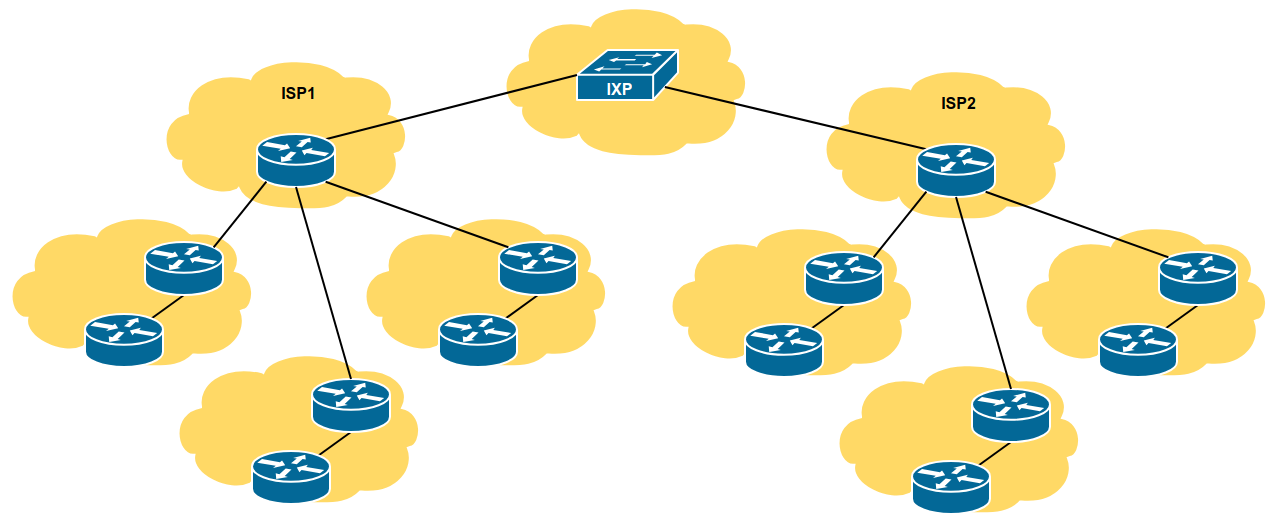
The network topology is designed to be modular to allow the lab to grow as needed depending on the number of participants. Each module in this lab contains 1 ISP and 3 customer networks (universities, etc). Modules will be interconnected.
Module one is made up of three Groups (1,2,3), and their ISP. As we go through the workshop, we will add an NREN to this Module as well.
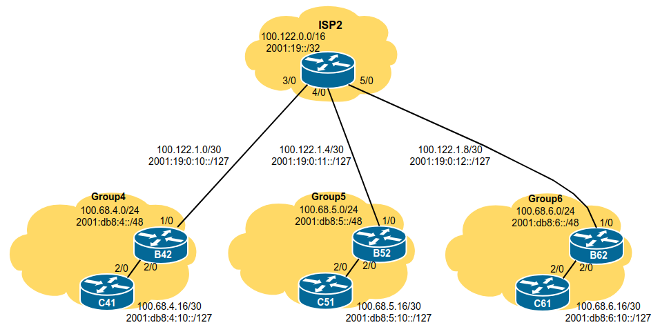
Module two is made up of three Groups (4,5,6), and their ISP. As we go through the workshop, we will add an NREN to this Module as well.
The entire workshop lab is interconnected as in the following diagram - the two ISPs interconnect via an Internet Exchange Point.
Each participant will be assigned to a network. Depending on the number of participants, either a single person or a group will be responsible for the configuration of a router. You may be asked to rotate and work on a different router so that you have the opportunity to understand the network from another point of view.
As you go through the exercises, you will see examples of configurations for one or more routers. Make sure to take those examples and adapt them to your own router, network topology and addressing scheme. Use the diagrams to guide you.
Refer to the Lab Access Instructions document for information about logging into the routers that have been assigned to you.
Refer to the IP Address Plan document for information about the IP address plan for the network infrastructure for these labs.
The following configuration examples show the suggested/recommended configuration to be implemented on the routers in each group. Replace the R in the examples with the router type (either B for Border or C for Core), and replace the X with your group number as appropriate.
Router> enable
Router# config terminal
Router(config)# hostname RX1We will use the username nrenlab for this workshop. It is a role account, note, something that is strongly discouraged on public infrastructure. However, we use it here only for ease of operating the lab, and that we will need to connect to other groups’ routers through the duration of this workshop. The standard password for this account is lab-PW. The enable password (which takes the operator into configuration mode) needs to be lab-EN1.
Please do not change the username or password to anything else, or leave the password unconfigured (access to vty ports is not possible if no password is set). It is essential for a smooth operating lab that all participants have access to all routers.
username nrenlab secret lab-PW
enable secret lab-EN
service password-encryptionCisco’s standard authentication model is from the late 80s and is really very obsolete. We will instead use Cisco’s implementation of AAA, first introduced in around 1995. The code snippet below uses the locally configured username/password pair for standard login, with the locally configured enable secret to go into configuration mode.
aaa new-model
aaa authentication login default local
aaa authentication enable default enableBy default, Cisco devices will try all transports available if they don’t recognise what is typed into the command line. This behaviour is annoying especially if making a typo during configuration work, so we will disable the behaviour completely. We will also set the idle-timeout on the console and other ports to 30 minutes - after 30 minutes of no activity on the port, the device will disconnect the connection.
line vty 0 4
 transport preferred none
 exec-timeout 30 0
line console 0
 transport preferred none
exec-timeout 30 0no logging console
logging buffered 8192 debuggingwhich disables console logs and instead records all logs in a 8192 byte buffer set aside on the router. To see the contents of this internal logging buffer at any time, the command “sh log” should be used at the command prompt.
Cisco devices will always try to look up the DNS for any name or address specified in the command line. You can see this when doing a trace on a router with no DNS server or a DNS server with no in-addr.arpa entries for the IP addresses. We will turn this lookup off for the labs for the time being to speed up traceroutes.
no ip domain-lookupTurn on IPv6 Routing and activate IPv6 CEF (not on by default in Cisco IOS)
ipv6 unicast-routing
ipv6 cefno ip source-route
no ipv6 source-routeEnable Path MTU Discovery on the router - this is not enabled by default for connections to the control plane (but it is enabled by default now for BGP).
ip tcp path-mtu-discoveryExit configuration mode and save
end
write memory
Configure your interfaces according to the diagram and the supplied address plan.
Notice that for the links to the ISP we will use the ISP’s addresses, while for internal links we use internal addresses.
On CX1:
interface GigabitEthernet2/0
 description P2P Link to BX2
 ip address 100.68.X.17 255.255.255.252
 no ip directed-broadcast
 no ip redirects
 no ip proxy-arp
 ipv6 address 2001:db8:X:10::0/127
 ipv6 nd prefix default no-advertise
 ipv6 nd ra suppress all
 no shutdown
!
On BX2:
interface GigabitEthernet2/0
 description P2P Link to CX1
 ip address 100.68.X.18 255.255.255.252
 no ip directed-broadcast
 no ip redirects
 no ip proxy-arp
 ipv6 address 2001:db8:X:10::1/127
 ipv6 nd prefix default no-advertise
 ipv6 nd ra suppress all
 no shutdown
!
And the link to the ISP needs to be configured also, for example:
On B12:
interface GigabitEthernet1/0
 description P2P Link to ISP1
 ip address 100.121.1.2 255.255.255.252
 no ip directed-broadcast
 no ip redirects
 no ip proxy-arp
 ipv6 address 2001:18:0:10::1/127
 ipv6 nd prefix default no-advertise
 ipv6 nd ra suppress all
 no shutdown
!An IP directed broadcast is an IP packet whose destination address is a valid broadcast address for some IP subnet, but which originates from a node that is not itself part of that destination subnet.
Because directed broadcasts, and particularly Internet Control Message Protocol (ICMP) directed broadcasts, have been abused by malicious persons, we recommend disabling the ip directed-broadcast command on any intereface where directed broadcasts are not needed (probably all).
Proxy ARP is the technique in which one host, usually a router, answers ARP requests intended for another machine. By “faking” its identity, the router accepts responsibility for routing packets to the “real” destination. Proxy ARP can help machines on a subnet reach remote subnets without the need to configure routing or a default gateway.
Disadvantages of proxy arp:
It increases the impact of ARP spoofing, in which a machine claims to be another in order to intercept packets.
It hides network misconfigurations in hosts
Hosts will have larger ARP tables
ICMP redirects can be sent to a host when the router knows that another router in the same subnet has a better path to a destination. If a hacker installs a router in the network that causes the legitimate router to learn these ilegitimate paths, the hacker’s router will end up diverting legitimate traffic thanks to ICMP redirects. Thus, we recommend that you disable this feature in all your interfaces.
IPv6 router advertisements are sent periodically by routers to inform hosts that the router is present, and to allow hosts to autoconfigure themselves using stateless autoconfiguration mechanisms. This is not necessary on point-to-point interfaces or any backbone infrastructure as there are no end user devices connecting to these links.
This prevents the router from sending any prefixes as part of router advertisements, so the client will not auto-configure itself with a global IPv6 address. This is helpful for IOS versions where you cannot suppress solicited RA messages.
Verify and save the configuration.
show running-config
write memory
Do some PING tests
R12# ping 100.68.1.17        <- C11
R12# ping 2001:db8:1:10::0   <- C11
R12# ping 100.121.1.1        <- ISP1
R12# ping 2001:18:0:10::0    <- ISP1
and then verify the output of the following commands:
show arp             : Show ARP cache
show interface       : Show interface state and config
show ip interface    : Show interface IP state and config
show ipv6 neighbors  : Show IPv6 neighbours
show ipv6 interface  : Show interface state and config
show cdp neighbors   : Show neighbours seen via CDP
Try and ping the other groups (remember to replace X with your own group number):
From BX2, try and ping the interface IP of the routers in the other groups.
From CX1, try and ping the interface IP of the routers in the other groups.
What happens ? Why ?
Try and look at the routing table, and the forwarding table
show ip route
show ipv6 route
To view the forwarding table:
show ip cef
show ipv6 cef
Can you find route entries for the other groups, and for the ISP network, in the route table ?
… In the forwarding table ?
What do you need to do to be able to reach those groups (and the ISPs) ?
What do those groups need to do to be able to reach your group ?