The purpose of this part of the lab is demonstrate how to do traffic engineering when a network operator is connected to two IXPs and most members participate in both.
We finished the previous lab with having 4 logical (and 2 physical) paths to each of our peers - we now want to improve on the traffic balance so that we are using both IXP fabrics.
Note that this will also be the scenario when one IXP has two independent sites (this is recommended for redundancy, rather than connecting two locations belonging to the same IXP at L2).
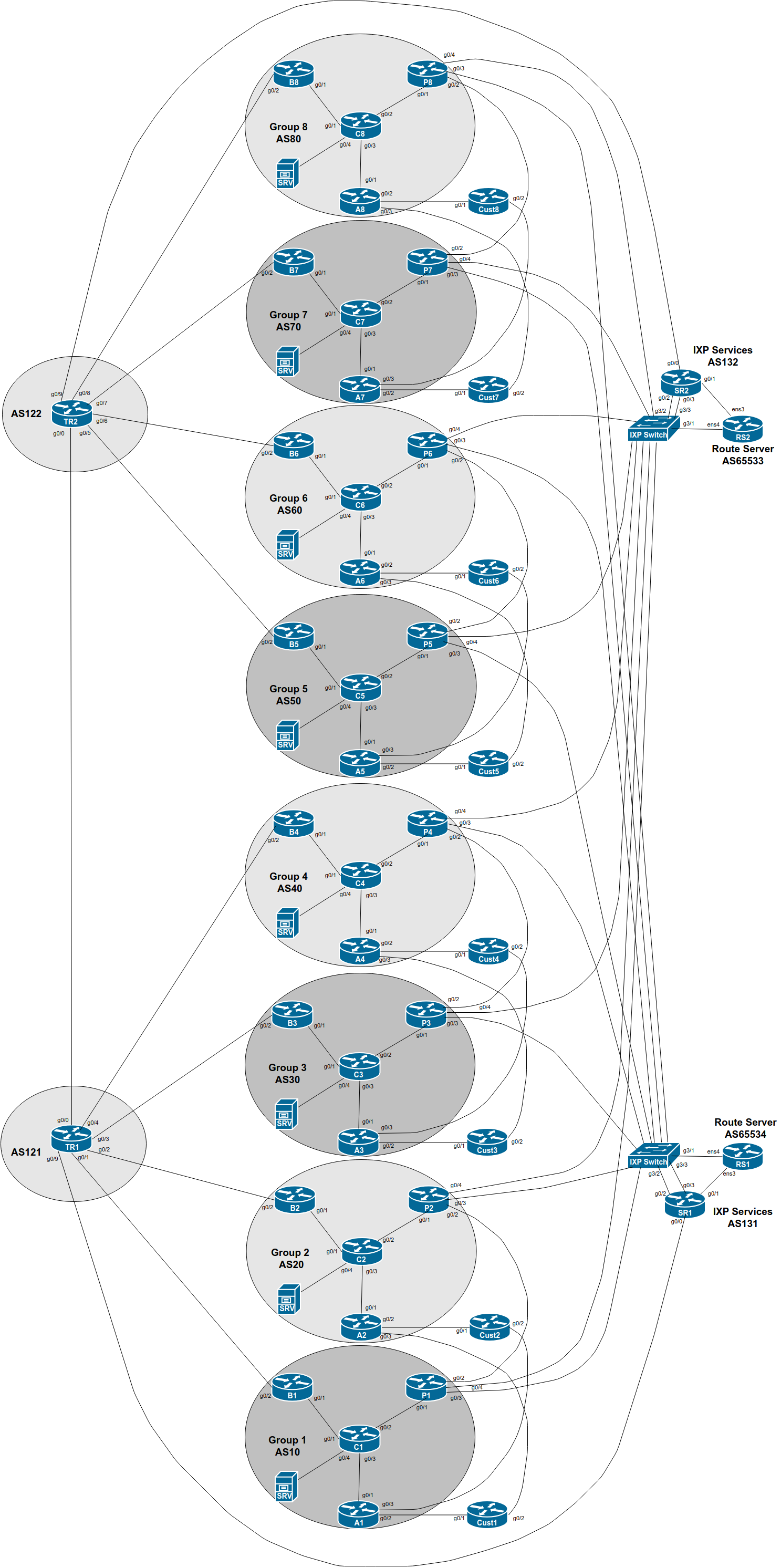
Here is a reminder of the diagram showing the two IXPs, IXP 1 and IXP 2.
At this stage in the lab we have routing information being sent between each AS over private peering links, bi-lateral peering links as well as the IXP route servers. A lot of paths are possible.
We have already configured highest priority to be over private peering links, followed by bi-lateral peering across the IXP fabric, and then via routes learned from the IXP’s router server.
But we now have two IXPs, with two sets of bi-lateral peerings with the same local preference, and two sets of paths via IXP route servers also with the same local preference as each other.
What should we do now? How should traffic engineering be implemented?
Some options:
We could make one IXP the primary path, and the other one the backup (which is what we have now)
We could loadbalance between the two IXPs (how?)
How would we implement either option?
The first option we have arrived at by good fortune.
For IPv4, IXP 1 is chosen purely because the neighbour IP address is lower than that used on IXP 2. Not very deterministic. Look at the IPv4 BGP table on your Peering Router, and confirm this. (We discussed this at the end of the previous lab, if you recall. What was the conclusion?)
What about IPv6? What happened there?
Again, look at the IPv6 BGP table. You will see that IXP 2 is used rather than IXP 1 simply because the neighbour IPv6 address is lower than that used on IXP 1.
Why is this not very deterministic? What could happen?
The second option needs more thought. Obviously for inbound routing announcements, we can set local-preference. But what about outbound? Should we send MEDs to our IX peers? Will they listen to them, or just over write with their own local preferences1?
These are some of the real-world challenges facing network operators participating in several different peering locations.
We will now explore changing the MED outbound to the members of the two IXPs. And changing the local-preference on inbound routing announcements.
We will set up the configuration as follows:
At IXP 1, set local-preference high on routes learned on your peerings with Groups 1, 3, 5 and 7, and set MED high on your announcements to Groups 2, 4, 6 and 8.
At IXP 2, set local-preference high on learned routes on your peerings with Groups 2, 4, 6 and 8, and set MED high on your announcements to Groups 1, 3, 5 and 7.
As before, let’s build our configuration in stages.
And the easiest way is to create peer-groups, one peer-group covering the high-local preference policy, and another peer-group covering the high-MED policy. These peer-groups will replace the existing ones in use for the bi-lateral peers at IXP 1 and IXP 2.
First we build the new peer-groups for IPv4:
router bgp X0
 address-family ipv4
  neighbor IXP-policyA peer-group
  neighbor IXP-policyA description Policy Group A
  neighbor IXP-policyA password BGPlab
  neighbor IXP-policyA route-map IXP-bilateral1-in in
  neighbor IXP-policyA route-map IXP-bilateral1-out out
!
  neighbor IXP-policyB peer-group
  neighbor IXP-policyB description Policy Group B
  neighbor IXP-policyB password BGPlab
  neighbor IXP-policyB route-map IXP-bilateral2-in in
  neighbor IXP-policyB route-map IXP-bilateral2-out out
and for IPv6:
router bgp X0
 address-family ipv6
  neighbor IXP-v6policyA peer-group
  neighbor IXP-v6policyA description Policy Group A - high LocalPref
  neighbor IXP-v6policyA password BGPlab
  neighbor IXP-v6policyA route-map IXP-bilateral1-in in
  neighbor IXP-v6policyA route-map IXP-bilateral1-out out
!
  neighbor IXP-v6policyB peer-group
  neighbor IXP-v6policyB description Policy Group B - high MED
  neighbor IXP-v6policyB password BGPlab
  neighbor IXP-v6policyB route-map IXP-bilateral2-in in
  neighbor IXP-v6policyB route-map IXP-bilateral2-out out
Note how we have replaced the single route-map policy statement used previously with two different route-map policy statements, one for each group of peers.
And then we apply the peer-groups to the appropriate neighbours. Here is an excerpt of what the IPv4 per-neighbour configuration might look like on Group 5’s peering router:
router bgp 50
 address-family ipv4
! IXP 1 bi-lateral peers
  neighbor 100.127.1.1 remote-as 10
  neighbor 100.127.1.1 activate
  neighbor 100.127.1.1 prefix-list AS10-block in
  neighbor 100.127.1.1 peer-group IXP-policyA
  neighbor 100.127.1.2 remote-as 20
  neighbor 100.127.1.2 activate
  neighbor 100.127.1.2 prefix-list AS20-block in
  neighbor 100.127.1.2 peer-group IXP-policyB
  neighbor 100.127.1.3 remote-as 30
  neighbor 100.127.1.3 activate
  neighbor 100.127.1.3 prefix-list AS30-block in
  neighbor 100.127.1.3 peer-group IXP-policyA
  neighbor 100.127.1.4 remote-as 40
  neighbor 100.127.1.4 activate
  neighbor 100.127.1.4 prefix-list AS40-block in
  neighbor 100.127.1.4 peer-group IXP-policyB
  neighbor 100.127.1.6 remote-as 60
  neighbor 100.127.1.6 activate
  neighbor 100.127.1.6 prefix-list AS60-block in
  neighbor 100.127.1.6 peer-group IXP-policyB
  neighbor 100.127.1.7 remote-as 70
  neighbor 100.127.1.7 activate
  neighbor 100.127.1.7 prefix-list AS70-block in
  neighbor 100.127.1.7 peer-group IXP-policyA
  neighbor 100.127.1.8 remote-as 80
  neighbor 100.127.1.8 activate
  neighbor 100.127.1.8 prefix-list AS80-block in
  neighbor 100.127.1.8 peer-group IXP-policyB
! IXP 2 bi-lateral peers
  neighbor 100.127.3.1 remote-as 10
  neighbor 100.127.3.1 activate
  neighbor 100.127.3.1 prefix-list AS10-block in
  neighbor 100.127.3.1 peer-group IXP-policyB
  neighbor 100.127.3.2 remote-as 20
  neighbor 100.127.3.2 activate
  neighbor 100.127.3.2 prefix-list AS20-block in
  neighbor 100.127.3.2 peer-group IXP-policyA
  neighbor 100.127.3.3 remote-as 30
  neighbor 100.127.3.3 activate
  neighbor 100.127.3.3 prefix-list AS30-block in
  neighbor 100.127.3.3 peer-group IXP-policyB
  neighbor 100.127.3.4 remote-as 40
  neighbor 100.127.3.4 activate
  neighbor 100.127.3.4 prefix-list AS40-block in
  neighbor 100.127.3.4 peer-group IXP-policyA
  neighbor 100.127.3.6 remote-as 60
  neighbor 100.127.3.6 activate
  neighbor 100.127.3.6 prefix-list AS60-block in
  neighbor 100.127.3.6 peer-group IXP-policyA
  neighbor 100.127.3.7 remote-as 70
  neighbor 100.127.3.7 activate
  neighbor 100.127.3.7 prefix-list AS70-block in
  neighbor 100.127.3.7 peer-group IXP-policyB
  neighbor 100.127.3.8 remote-as 80
  neighbor 100.127.3.8 activate
  neighbor 100.127.3.8 prefix-list AS80-block in
  neighbor 100.127.3.8 peer-group IXP-policyA
!
Develop your own configuration for the equivalent IPv6 per-neighbour peerings using the above as an example. Follow the suggestions which have been made in all the lab work up to now.
And the route-maps mentioned look like this (using the BGP communities when an IXP was first introduced earlier in the workshop) - these route-maps can be shared by both the IPv4 and IPv6 peerings as they are not address-family specific:
route-map IXP-bilateral1-in permit 5
 description Local pref for IXP primary Bi-lateral Peer
 set local-preference 170
 set community 50:1200
!
route-map IXP-bilateral1-out permit 5
 description MED for IXP primary Bi-lateral Peer
 match community aggregate customer-pi
 set metric 0
!
route-map IXP-bilateral2-in permit 5
 description Local pref for IXP backup Bi-lateral Peer
 set local-preference 160
 set community 50:1200
!
route-map IXP-bilateral2-out permit 5
 description MED for IXP primary Bi-lateral Peer
 match community aggregate customer-pi
 set metric 20
!
What happens? Try some traceroutes as well as looking at the BGP to view preferred paths to peers now.
Explain what you see to the lab instructors.
Do you get the results you expect?
This is the approach to use when you are connected to two IXPs and you wish to try and balance traffic across the two fabrics. Of course, what you do depends on the situation.
For one IXP with two independent switches, you probably want to balance between the two switches/IXPs
For two local IXPs, you probably want to balance between the two IXPs as well.
For a local and regional IXP, you will prefer the local IXP over the regional IXP (for local traffic)
For two regional IXPs, you will prefer the IXP with lowest latency and higher bandwidth over the other IXP.
etc
And yes, this has made the configuration on the peering router quite lengthy and potentially somewhat confusing. Hence why we have used as many configuration optimisation methods as we possibly can.
Also, the lab has shown that while you can control your outbound traffic by applying policies on the inbound announcements, your inbound traffic flows are in the hands of your peering partners. In some cases in this lab, while you may have set a high MED outbound to a bi-lateral peer, you will still see that traffic will still use that incoming path because the peer has set Local Preference higher on this path than on the other three.
Look at this example from Group 6 in an earlier version of this workshop lab:
P6#sh ip bgp
BGP table version is 22, local router ID is 100.68.6.3
Status codes: s suppressed, d damped, h history, * valid, > best, i - internal,
              r RIB-failure, S Stale, m multipath, b backup-path, f RT-Filter,
              x best-external, a additional-path, c RIB-compressed,
              t secondary path,
Origin codes: i - IGP, e - EGP, ? - incomplete
RPKI validation codes: V valid, I invalid, N Not found

     Network          Next Hop            Metric LocPrf Weight Path
 *   100.68.1.0/24    100.127.1.1                   150      0 10 i
 *                    100.127.3.1                   150      0 10 i
 *                    100.127.3.1              0    160      0 10 i
 *>                   100.127.1.1             20    170      0 10 i
 *   100.68.2.0/24    100.127.3.2                   150      0 20 i
 *                    100.127.1.2                   150      0 20 i
 *>                   100.127.3.2              0    170      0 20 i
 *                    100.127.1.2             20    160      0 20 i
 *   100.68.3.0/24    100.127.1.3                   150      0 30 i
 *                    100.127.3.3                   150      0 30 i
 *                    100.127.3.3              0    160      0 30 i
 *>                   100.127.1.3             20    170      0 30 i
 *   100.68.4.0/24    100.127.3.4                   150      0 40 i
 *                    100.127.1.4                   150      0 40 i
 *>                   100.127.3.4              0    170      0 40 i
 *                    100.127.1.4             20    160      0 40 i
 *   100.68.5.0/24    100.127.1.5                   150      0 50 i
 *                    100.127.3.5                   150      0 50 i
 *                    100.127.3.5              0    160      0 50 i
 *>                   100.68.5.32                   200      0 50 i
 *                    100.127.1.5             20    170      0 50 i
 *>i 100.68.6.0/24    100.68.6.2               0    100      0 i
 *>i 100.68.6.28/30   100.68.6.2               0    100      0 i
 *>i 100.68.6.64/26   100.68.6.4               0    100      0 i
...etc...
Look at the prefix learned from AS10. You have set Local-Pref 170 on the announcement heard on the bi-lateral peering across the IXP 1 fabric. Here is the detail:
P6#sh ip bgp 100.68.1.0/24
BGP routing table entry for 100.68.1.0/24, version 13
BGP Bestpath: deterministic-med
Paths: (4 available, best #4, table default)
  Advertised to update-groups:
     2
  Refresh Epoch 1
  10
    100.127.3.1 from 100.127.3.254 (100.127.3.254)
      Origin IGP, metric 0, localpref 150, valid, external
      Community: 60:1300
      rx pathid: 0, tx pathid: 0
  Refresh Epoch 1
  10
    100.127.1.1 from 100.127.1.254 (100.127.1.254)
      Origin IGP, metric 0, localpref 150, valid, external
      Community: 60:1300
      rx pathid: 0, tx pathid: 0
  Refresh Epoch 1
  10
    100.127.3.1 from 100.127.3.1 (100.68.1.3)
      Origin IGP, metric 0, localpref 160, valid, external
      Community: 10:1200
      rx pathid: 0, tx pathid: 0
  Refresh Epoch 1
  10
    100.127.1.1 from 100.127.1.1 (100.68.1.3)
      Origin IGP, metric 20, localpref 170, valid, external, best
      Community: 10:1200
      rx pathid: 0, tx pathid: 0x0
Note that the 4th entry is the best path, learned on the bi-lateral with P1 across IXP 1 (look at the router-id). Yet that neighbour has set MED 20, indicating to you that they don’t want you to use this path, but to use the other one, the first entry in the list of 4. But you have marked it with local-preference 160, so it is not preferred.
Check the equivalent prefix for IPv6:
P6#sh bgp ipv6 uni 2001:db8:1::/48
BGP routing table entry for 2001:DB8:1::/48, version 2
BGP Bestpath: deterministic-med
Paths: (4 available, best #4, table default)
Flag: 0x100
  Advertised to update-groups:
     4
  Refresh Epoch 1
  10
    2001:DB8:FFFF:1::1 (FE80::E39:58FF:FE28:4203) from 2001:DB8:FFFF:1::FE (100.127.1.254)
      Origin IGP, localpref 150, valid, external
      Community: 60:1300
      rx pathid: 0, tx pathid: 0
  Refresh Epoch 1
  10
    2001:DB8:FFFE:1::1 (FE80::E39:58FF:FE28:4204) from 2001:DB8:FFFE:1::FE (100.127.3.254)
      Origin IGP, localpref 150, valid, external
      Community: 60:1300
      rx pathid: 0, tx pathid: 0
  Refresh Epoch 1
  10
    2001:DB8:FFFE:1::1 (FE80::E39:58FF:FE28:4204) from 2001:DB8:FFFE:1::1 (100.68.1.3)
      Origin IGP, metric 0, localpref 160, valid, external
      Community: 60:1200
      rx pathid: 0, tx pathid: 0
  Refresh Epoch 1
  10
    2001:DB8:FFFF:1::1 (FE80::E39:58FF:FE28:4203) from 2001:DB8:FFFF:1::1 (100.68.1.3)
      Origin IGP, metric 20, localpref 170, valid, external, best
      Community: 60:1200
      rx pathid: 0, tx pathid: 0x0
The best path is the fourth entry - again the peer has set MED of 20, indicating a de-preference of the path, yet you have marked it with the highest preference, so this becomes the preferred outbound path to this destination.
Peering and traffic path optimisation has to be done in consultation with your peers. We came up with what we considered was a reasonable policy to load balance across the two fabrics with our bi-lateral peers. But we didn’t consult with them, giving the results we see here.
Welcome to the real world of peering and traffic engineering!