The purpose of this part of the lab is demonstrate how to do traffic engineering when a network operator is connected to two IXPs and most members participate in both.
Note that this could also be the scenario when one IXP has two independent sites (this is recommended for when an IXP would like to introduce redundancy for its members; rather than connecting two locations belonging to the same IXP at L2).
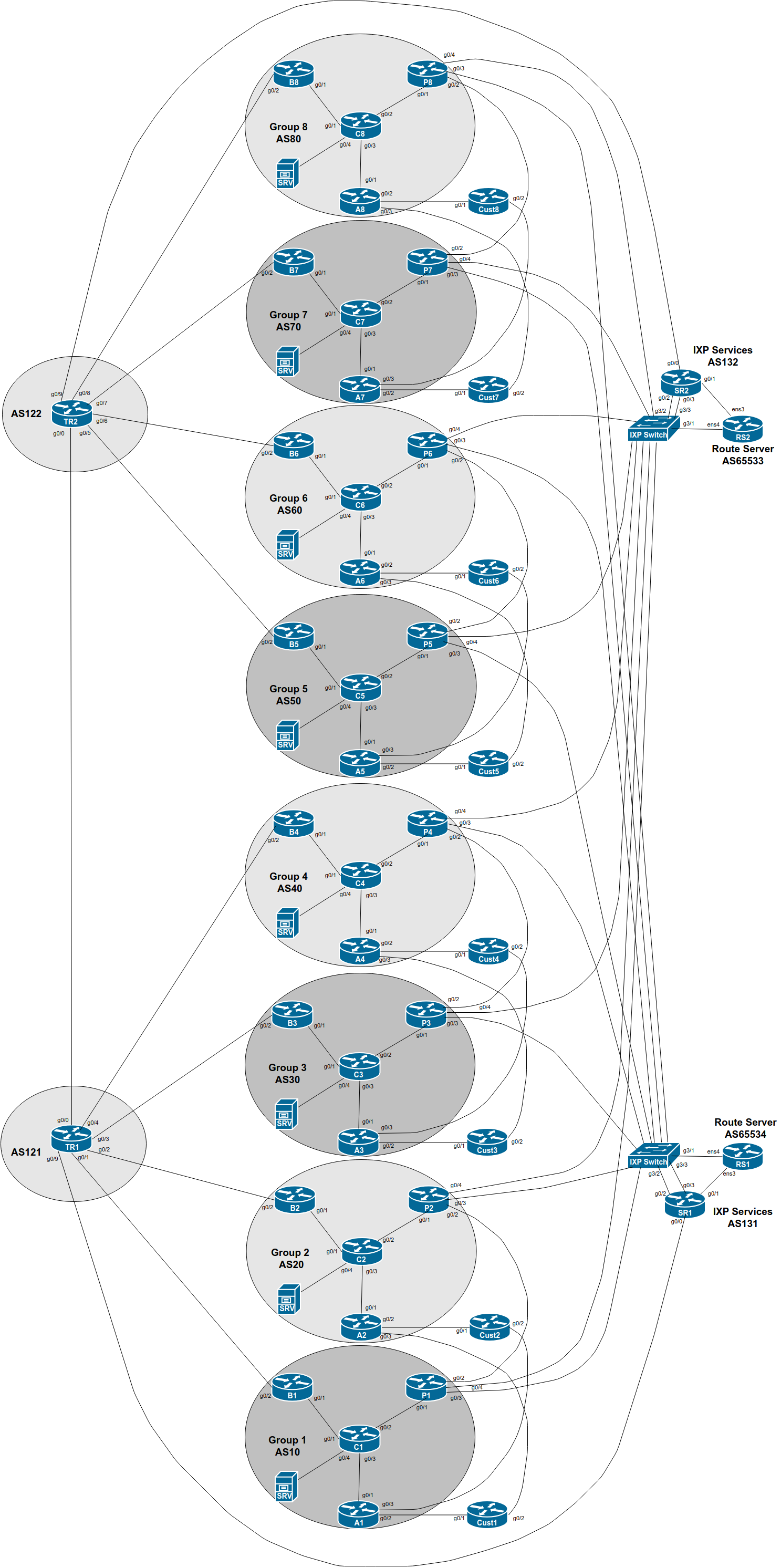
The network topology has been added to by the instructors to create two IXPs. The GigabitEthernet 0/3 interface of the Group’s Peering Router connects to what has now become IXP 1 (the original IXP in the previous exercises), and the GigabitEthernet 0/4 interface connects to IXP 2.
The additional IXP also has a Route Server and a Services Router; the latter is used to give transit to any of the services that the IXP might be offering to its members (eg DNS, content caching, NTP, Looking Glass, etc).
You will now notice the address space used by IXP 2’s services infrastructure also appearing in the routing table within your group. Consult the IP Address Plan document for the address space used by IXP 2 and see if this is what you now see in your BGP table.
Each group should now configure the ethernet link from the Peering router to the new IXP according to the above diagram.
Consult the IP Address Plan document for the address space used by the new IXP. Following the document, configure the new interface on the Peering router accordingly.
interface GigabitEthernet 0/4
 description ASX0 link to IXP 2
 ip address 100.127.3.X 255.255.255.0
 no ip directed-broadcast
 no ip redirects
 no ip proxy-arp
 ipv6 address 2001:DB8:FFFE:1::X/64
 ipv6 nd prefix default no-advertise
 ipv6 nd ra suppress all
 no shutdown
!
And modify the description of the existing interface to IXP 1 to indicate its change in status:
interface GigabitEthernet 0/3
 description ASX0 link to IXP 1
!
Do not configure IS-IS towards any IXP peer! They are not part of your autonomous system.
As before, so that traceroutes across the IXP do not break, we might wish to carry the IXP LAN address block within our IS-IS (not iBGP). To do this, we simply mark the IXP facing interface as passive in the IS-IS configuration. Here is an example:
router isis asX0
 passive-interface GigabitEthernet 0/4
We now configure eBGP on our Peering Router with IXP 2’s Route Server. If you set up bi-lateral peerings earlier with members of the original IXP, also set up bi-lateral peerings with members of the new IXP as well.
We can use much of the configuration we created earlier when we set up the first IXP - the only difference is the eBGP neighbour address.
IXP 2’s Route Server uses AS655331.
We can reuse all the policy configuration we had earlier. The extra
configuration for peering with IXP 2’s RS might include the following
(replacing <policy> with your current policy used for
the original IXP):
router bgp X0
 address-family ipv4
  neighbor 100.127.3.254 remote-as 65533
  neighbor 100.127.3.254 description eBGP with IXP 2 RS
  neighbor 100.127.3.254 password ixp-rs
  neighbor 100.127.3.254 <policy> out
  neighbor 100.127.3.254 <policy> in
  neighbor 100.127.3.254 activate
!
 address-family ipv6
  neighbor 2001:DB8:FFFE:1::FE remote-as 65533
  neighbor 2001:DB8:FFFE:1::FE description eBGP with IXP 2 RS
  neighbor 2001:DB8:FFFE:1::FE password ixp-rs
  neighbor 2001:DB8:FFFE:1::FE <policy> out
  neighbor 2001:DB8:FFFE:1::FE <policy> in
  neighbor 2001:DB8:FFFE:1::FE activate
!
And set up the bi-lateral BGP sessions with the other members of IXP
2. As we did in the Bilateral Peering lab, we create the peer-group
first, to make the configuration more scalable, like this (again
replacing <policy> with your current policy used for
the original IXP):
router bgp X0
 address-family ipv4
  neighbor IXP-2-bilateral peer-group
  neighbor IXP-2-bilateral description eBGP with bi-lateral peers at IXP
  neighbor IXP-2-bilateral password BGPlab
  neighbor IXP-2-bilateral <policy> in
  neighbor IXP-2-bilateral <policy> out
!
 address-family ipv6
  neighbor IXP-2-bilateralv6 peer-group
  neighbor IXP-2-bilateralv6 description eBGP with bi-lateral peers at IXP
  neighbor IXP-2-bilateralv6 password BGPlab
  neighbor IXP-2-bilateralv6 <policy> in
  neighbor IXP-2-bilateralv6 <policy> out
!
And then we apply the peer-group to all the bi-lateral peers, like this:
router bgp X0
 address-family ipv4
  neighbor 100.127.3.Y remote-as Y0
  neighbor 100.127.3.Y description eBGP with ASY0
  neighbor 100.127.3.Y peer-group IXP-2-bilateral
  neighbor 100.127.3.Y prefix-list ASY0-block in
!
 address-family ipv6
  neighbor 2001:DB8:FFFE:1::Y remote-as Y0
  neighbor 2001:DB8:FFFE:1::Y description eBGP with ASY0
  neighbor 2001:DB8:FFFE:1::Y peer-group IXP-2-bilateralv6
  neighbor 2001:DB8:FFFE:1::Y prefix-list ASY0-v6block in
!
Note: it would be nice to rename the original
bi-lateral peering peer-group from IXP-bilateral to
IXP-1-bilateral, but Cisco IOS doesn’t support the renaming
of peer-groups. If you did want to do this, you’d have to delete the
peer-group (which means deleting all the neighbours as well), and then
reinstating the configuration2.
What do you now see in the BGP table?
Which is the best path to peers across the two IXPs? Over the new peering you set up, or over the original one?
Explain what you see to the workshop instructors.
You should now see four paths to each of your peers, something like this for IPv4 (taken from an earlier version of this workshop):
P6#sh ip bgp 100.68.3.0
BGP routing table entry for 100.68.3.0/24, version 3
BGP Bestpath: deterministic-med
Paths: (4 available, best #4, table default)
  Advertised to update-groups:
     2
  Refresh Epoch 1
  30
    100.127.3.3 from 100.127.3.254 (100.127.3.254)
      Origin IGP, metric 0, localpref 150, valid, external
      Community: 60:1300
      rx pathid: 0, tx pathid: 0
  Refresh Epoch 1
  30
    100.127.1.3 from 100.127.1.254 (100.127.1.254)
      Origin IGP, metric 0, localpref 150, valid, external
      Community: 60:1300
      rx pathid: 0, tx pathid: 0
  Refresh Epoch 1
  30
    100.127.3.3 from 100.127.3.3 (100.68.3.3)
      Origin IGP, localpref 170, valid, external
      Community: 60:1200
      rx pathid: 0, tx pathid: 0
  Refresh Epoch 1
  30
    100.127.1.3 from 100.127.1.3 (100.68.3.3)
      Origin IGP, localpref 170, valid, external, best
      Community: 60:1200
      rx pathid: 0, tx pathid: 0x0
Using the BGP Path Selection algorithm covered in the BGP Attributes presentation, are you able to explain why the last of the four paths in this example is the best path?
Try the same on some of the paths you see for your peers on your Peering router.
What about IPv6? Below is the output again from Group 6’s Peering Router for the same prefix originated by Group 3:
P6>sh bgp ipv6 uni 2001:db8:3::/48
BGP routing table entry for 2001:DB8:3::/48, version 4
BGP Bestpath: deterministic-med
Paths: (4 available, best #4, table default)
Flag: 0x100
  Advertised to update-groups:
     2
  Refresh Epoch 1
  30
    2001:DB8:FFFE:1::3 (FE80::E39:58FF:FE96:6704) from 2001:DB8:FFFE:1::FE (100.127.3.254)
      Origin IGP, localpref 150, valid, external
      Community: 60:1300
      rx pathid: 0, tx pathid: 0
  Refresh Epoch 1
  30
    2001:DB8:FFFF:1::3 (FE80::E39:58FF:FE96:6703) from 2001:DB8:FFFF:1::FE (100.127.1.254)
      Origin IGP, localpref 150, valid, external
      Community: 60:1300
      rx pathid: 0, tx pathid: 0
  Refresh Epoch 1
  30
    2001:DB8:FFFF:1::3 (FE80::E39:58FF:FE96:6703) from 2001:DB8:FFFF:1::3 (100.68.3.3)
      Origin IGP, localpref 170, valid, external
      Community: 60:1200
      rx pathid: 0, tx pathid: 0
  Refresh Epoch 1
  30
    2001:DB8:FFFE:1::3 (FE80::E39:58FF:FE96:6704) from 2001:DB8:FFFE:1::3 (100.68.3.3)
      Origin IGP, localpref 170, valid, external, best
      Community: 60:1200
      rx pathid: 0, tx pathid: 0x0
Using the BGP Path Selection algorithm covered in the BGP Attributes presentation, are you able to explain why the last of the four paths in this example is the best path?
Discussion: To complete this lab, explain to the instructor why you see these results, and what the cause is.
We will look further at what is going on here in the next lab.