
[Main Page](../index.html "Main Page")
# Indoor Coverage Planning
The goal of this exercise is to provide the best possible coverage and capacity for a building using a limited number of access points.
## Plan Details & Assumptions
- The RMI Campus IT building will be used for this survey
- A site survey has already been conducted
- The network will have no more than twenty access points
- Coverage planning will be based on 2.4 GHz, capacity based on 5 GHz
- End users should receive a minimum signal of -70 dBm
- Co-Channel interference shall be no higher than -95 dBm
- End devices should receive a minimum of 2 Mbps each
- RMI concrete walls are assumed to attenuate 20 dB
- RMI floors and ceilings are assumed to attenuate 20 dB
- Free space loss will be calculated using http://wifinigel.blogspot.com/2014/05/wifi-free-space-loss-calculator.html
- Distance for free space loss will be from AP to the centre of each room
- Hallway predictions will be made every five meters
- Channels 6 and 108 will be used to predict signal levels
- Signal rates at RSSI can be found here: https://www.wlanpros.com/mcs-index-charts/
## Plan Execution
Groups will work together to plan initial placement of the APs. Then groups will divide the rooms and hallway points up, and each group will evaluate the expected signal for their locations.
## Example Plan
The finished plan should show access point placement and an exepcted signal level at both 2.4 & 5.6 GHz for each location, similar to the plan below. In this plan, only 2.4 GHz is considered, and the walls are made of wood and plaster.
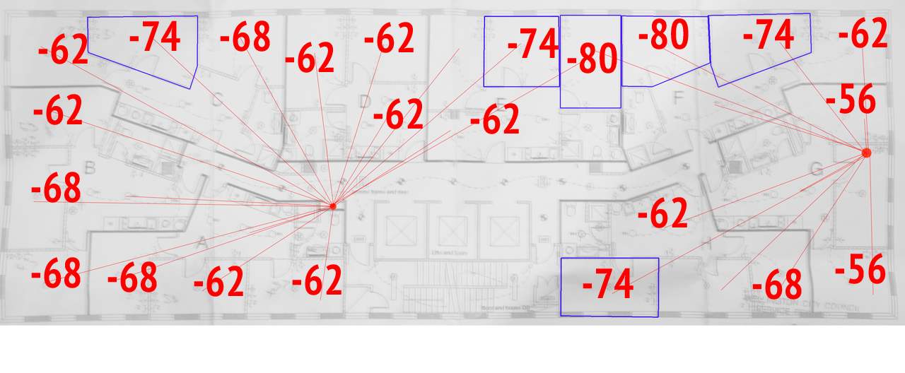
Each room evaluated should also note how many potential end devices it could have so that number and size of rf channels can be planned.
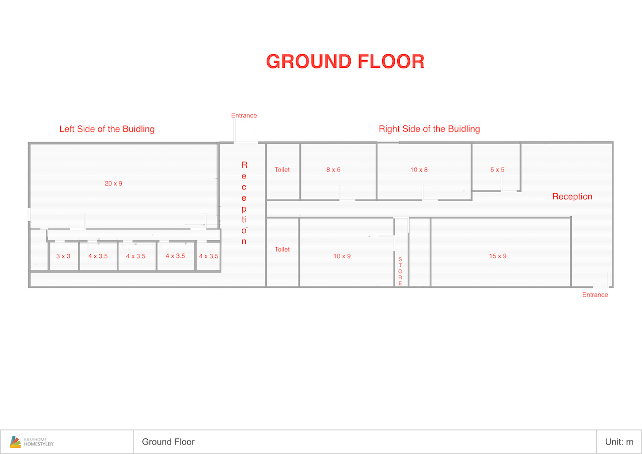
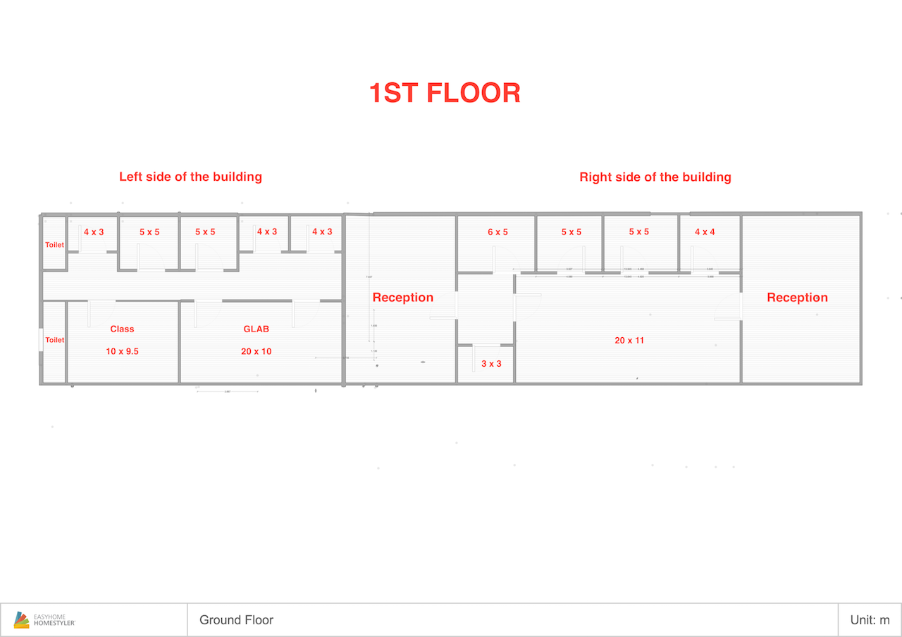
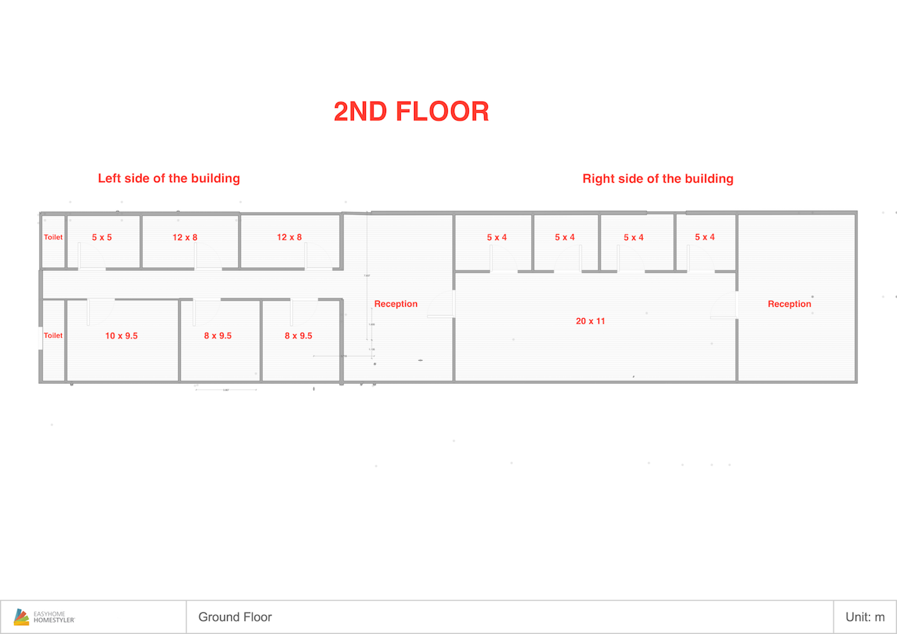
## Floor Plans
RMI Floor Plans are available below. When the installation plan is finished, groups should work together to edit the images below in an image editor and upload them to the Google Doc here: https://docs.google.com/document/d/1zgqyyI-J681OStcnpyfoVdDhD3JRsu6Du-in6xRqj-U/edit?usp=sharing
## Checking Coverage
For each access point planned, groups will take their switch and access points to the planned installation locations. One group member will temporarily hold or secure their AP in place, while the other measures signal locally and through obstructions like walls.
Actual signal levels recorded will be added to the diagrams in the Google Doc: https://docs.google.com/document/d/1zgqyyI-J681OStcnpyfoVdDhD3JRsu6Du-in6xRqj-U/edit?usp=sharing