
The purpose of this exercise is to introduce participants to the basic configuration requirements of a Cisco router.
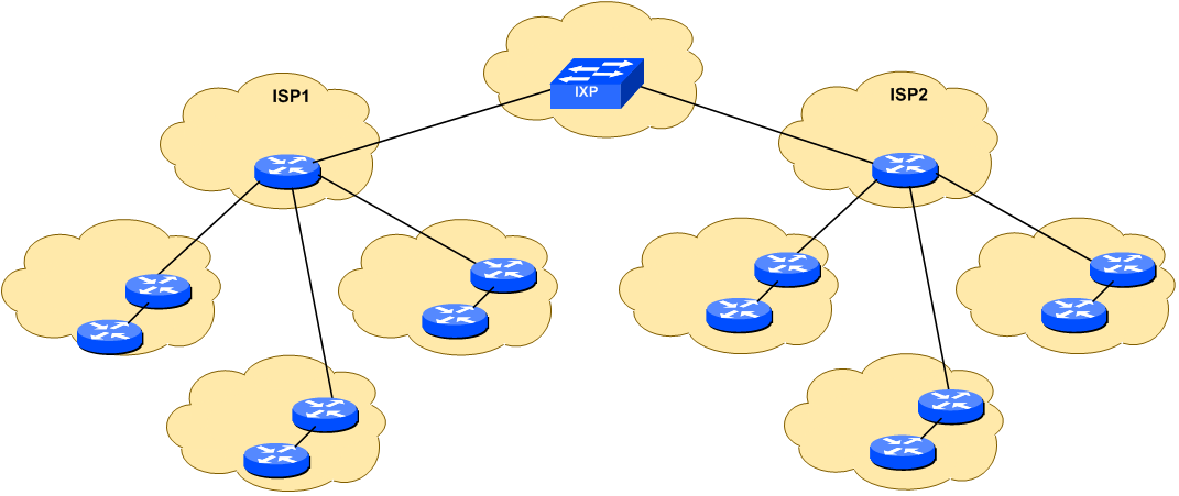
The network topology is designed to be modular to allow the lab to grow as needed depending on the number of participants. Each module in this lab contains 1 ISP and 3 customer networks (universities, etc). Modules will be interconnected.
Module one is made up of three Groups (1,2,3), and their ISP. As we go through the workshop, we will add an NREN to this Module as well.
Module two is made up of three Groups (4,5,6), and their ISP. As we go through the workshop, we will add an NREN to this Module as well.

The entire workshop lab is interconnected as in the following diagram - the two ISPs interconnect via an Internet Exchange Point.
Each participant will be assigned to a network. Depending on the number of participants, either a single person or a group will be responsible for the configuration of a router. You may be asked to rotate and work on a different router so that you have the opportunity to understand the network from another point of view.
As you go through the exercises, you will see examples of configurations for one or more routers. Make sure to take those examples and adapt them to your own router, network topology and addressing scheme. Use the diagrams to guide you.
Refer to the Lab Access Instructions document for information about logging into the routers that have been assigned to you.
Refer to the IP Address Plan document for information about the IP address plan for the network infrastructure for these labs.
The following configuration examples show the suggested/recommended configuration to be implemented on the routers in each group. Replace the R in the examples with the router type (either B for Border or C for Core), and replace the X with your group number as appropriate.
Router> enable
Router# config terminal
Router(config)# hostname RX1aaa new-model
aaa authentication login default local
aaa authentication enable default enable
username nrenlab secret lab-PW
enable secret lab-EN
service password-encryption
line vty 0 4
transport preferred none
line console 0
transport preferred noneno logging console
logging buffered 8192 debuggingno ip domain-lookupTurn on IPv6 Routing and activate IPv6 CEF (not on by default in Cisco IOS)
ipv6 unicast-routing
ipv6 cefno ip source-route
no ipv6 source-routeEnable Path MTU Discovery on the router - this is not enabled by default for connections to the control plane (but it is enabled by default now for BGP).
ip tcp path-mtu-discoveryExit configuration mode and save
end
write memoryConfigure your interfaces according to the diagram
Notice that for the links to the ISP we will use the ISP's addresses, while for internal links we use internal addresses.
On CX1:
interface GigabitEthernet2/0
description P2P Link to BX2
ip address 100.68.X.17 255.255.255.252
no ip directed-broadcast
no ip redirects
no ip proxy-arp
ipv6 address 2001:db8:X:10::0/127
ipv6 nd prefix default no-advertise
ipv6 nd ra suppress all
no shutdown
!On BX2:
interface GigabitEthernet2/0
description P2P Link to CX1
ip address 100.68.X.18 255.255.255.252
no ip directed-broadcast
no ip redirects
no ip proxy-arp
ipv6 address 2001:db8:X:10::1/127
ipv6 nd prefix default no-advertise
ipv6 nd ra suppress all
no shutdown
!And the link to the ISP needs to be configured also, for example:
On B12:
interface GigabitEthernet1/0
description P2P Link to ISP1
ip address 100.121.1.2 255.255.255.252
no ip directed-broadcast
no ip redirects
no ip proxy-arp
ipv6 address 2001:18:0:10::1/127
ipv6 nd prefix default no-advertise
ipv6 nd ra suppress all
no shutdown
!An IP directed broadcast is an IP packet whose destination address is a valid broadcast address for some IP subnet, but which originates from a node that is not itself part of that destination subnet.
Because directed broadcasts, and particularly Internet Control Message Protocol (ICMP) directed broadcasts, have been abused by malicious persons, we recommend disabling the ip directed-broadcast command on any intereface where directed broadcasts are not needed (probably all).
Proxy ARP is the technique in which one host, usually a router, answers ARP requests intended for another machine. By "faking" its identity, the router accepts responsibility for routing packets to the "real" destination. Proxy ARP can help machines on a subnet reach remote subnets without the need to configure routing or a default gateway.
Disadvantages of proxy arp:
It increases the impact of ARP spoofing, in which a machine claims to be another in order to intercept packets.
It hides network misconfigurations in hosts
Hosts will have larger ARP tables
ICMP redirects can be sent to a host when the router knows that another router in the same subnet has a better path to a destination. If a hacker installs a router in the network that causes the legitimate router to learn these ilegitimate paths, the hacker's router will end up diverting legitimate traffic thanks to ICMP redirects. Thus, we recommend that you disable this feature in all your interfaces.
IPv6 router advertisements are sent periodically by routers to inform hosts that the router is present, and to allow hosts to autoconfigure themselves using stateless autoconfiguration mechanisms. This is not necessary on point-to-point interfaces or any backbone infrastructure as there are no end user devices connecting to these links.
This prevents the router from sending any prefixes as part of router advertisements, so the client will not auto-configure itself with a global IPv6 address. This is helpful for IOS versions where you cannot suppress solicited RA messages.
Do some PING tests
R12# ping 100.68.1.17 <- C11
R12# ping 2001:db8:1:10::0 <- C11
R12# ping 100.121.1.1 <- ISP1
R12# ping 2001:18:0:10::0 <- ISP1and then verify the output of the following commands:
show arp : Show ARP cache
show interface : Show interface state and config
show ip interface : Show interface IP state and config
show ipv6 neighbors : Show IPv6 neighbours
show ipv6 interface : Show interface state and config
show cdp neighbors : Show neighbours seen via CDPTry and ping the other groups (remember to replace X with your own group number):
From BX2, try and ping the interface IP of the routers in the other groups.
From CX1, try and ping the interface IP of the routers in the other groups.
What happens ? Why ?
Try and look at the routing table, and the forwarding table
show ip route
show ipv6 routeTo view the forwarding table:
show ip cef
show ipv6 cefCan you find route entries for the other groups, and for the ISP network, in the route table ?
... In the forwarding table ?
What do you need to do to be able to reach those groups (and the ISPs) ?
What do those groups need to do to be able to reach your group ?
On your routers CX1 and BX2, you will need to create static routes for:
all of the other groups
the ISPs' address space (yes, both of them)
the Tier 1 ISP address space (yes, this too)
all the links interconnecting the other groups to the ISPs
What will those routes point to (next hop) on BX2 ?
What will those routes point to (next hop) on CX1 ?
Remember the syntax for adding routes is:
ip route SUBNET MASK NEXT-HOPFor example on B12, to reach Group 2:
B12(config)# ip route 100.68.2.0 255.255.255.0 100.121.1.1
B12(config)# ipv6 route 2001:db8:2::/48 2001:18:0:10::0Based on the information above, create the required routes to be able to reach all the other groups, interconnection links, and the ISP address space.
Verify and save the configuration.
show running-config write memory
Below is a sample configuration for ISP1. ISP2's configuration will be very similar. The teams operating ISP1 and ISP2 should build their configurations based on the sample below.
Note that both ISP routers are connected to the workshop backbone. ISP1 uses the 100.68.100.235/24 address, and ISP2 uses the 100.68.100.236/24 address.
hostname ISP1
aaa new-model
aaa authentication login default local
aaa authentication enable default enable
username nrenlab secret nsrc-PW
enable secret nsrc-EN
service password-encryption
line vty 0 4
transport preferred none
line console 0
transport preferred none
no logging console
logging buffered 8192 debugging
no ip domain-lookup
ipv6 unicast-routing
ipv6 cef
no ip source-route
no ipv6 source-route
!
interface Loopback0
ip address 100.121.0.1 255.255.255.255
ipv6 address 2001:18::1/128
!
interface FastEthernet0/0
description Workshop Backbone
ip address 100.68.100.235 255.255.255.0
no ip directed-broadcast
no ip redirects
no ip proxy-arp
no shutdown
!
interface GigabitEthernet1/0
description Link to IXP
ip address 100.127.1.1 255.255.255.0
no ip directed-broadcast
no ip redirects
no ip proxy-arp
ipv6 address 2001:DB8:FFFF:1::1/64
ipv6 nd prefix default no-advertise
ipv6 nd ra suppress all
no shutdown
!
! Link to Group 1 (repeat for Groups 2 and 3 on GigE4/0 and 5/0)
interface GigabitEthernet3/0
description P2P Link to B12
ip address 100.121.1.1 255.255.255.252
no ip directed-broadcast
no ip redirects
no ip proxy-arp
ipv6 address 2001:18:0:10::/127
ipv6 nd prefix default no-advertise
ipv6 nd ra suppress all
no shutdown
!
! Routes to Group 1 (repeat for groups 2 and 3)
ip route 100.68.1.0 255.255.255.0 100.121.1.2
ipv6 route 2001:db8:1::/48 2001:18:0:10::1
!
! Routes to Group 4 (repeat for groups 5 and 6)
ip route 100.68.4.0 255.255.255.0 100.127.1.2
ipv6 route 2001:db8:4::/48 2001:DB8:FFFF:1::2
!
! Routes to ISP2 address space
ip route 100.122.0.0 255.255.0.0 100.127.1.2
ipv6 route 2001:19::/32 2001:DB8:FFFF:1::2
!
! Pull-up routes for address blocks of ISP1
ip route 100.121.0.0 255.255.0.0 null0
ipv6 route 2001:18::/32 null0
!