The purpose of this lab is to set up the necessary infrastructure ready to investigate routing protocol security, device control plane security, and securing the routing system.
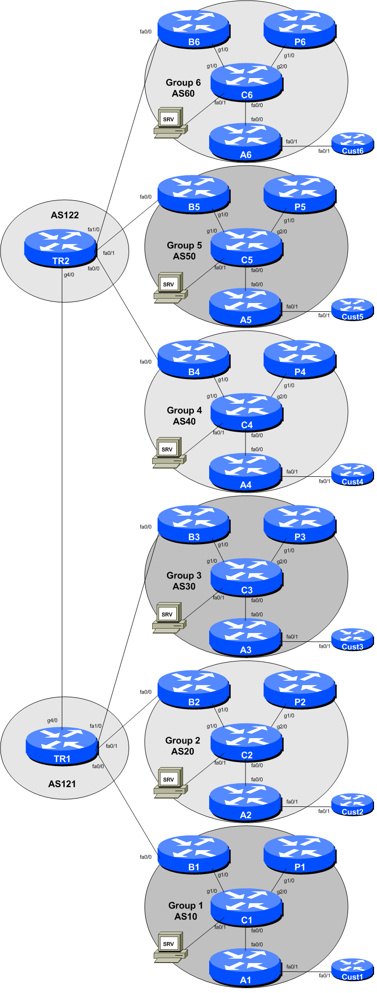
The initial lab topology sets up 6 autonomous systems (AS), each with four routers. In each AS, one router is the border router (for connecting to transit providers), one router is the core router (representing the rest of the network operator’s core network), one router is a peering router (for connecting to private peers and IXPs), and one router is the access router (for connecting to customer end-sites). There is also one customer router provided too. Each group has an Ubuntu appliance, which will be used later on in the workshop when exploring BGP Security.
The lab will start simply by configuring each autonomous system, and making sure that transit works via their transit provider. The address plan for the entire network is described in the Address Plan document. The initial set up is shown below.
Each participant will be assigned to a group. Depending on the number of participants, either a single person or a group will be responsible for the configuration of a router. You may be asked to rotate and work on a different router so that you have the opportunity to understand the network from another point of view.
As you go through the exercises, you will see examples of configurations for one or more routers. Make sure to take those examples and adapt them to your own router, network topology and addressing scheme. Use the diagrams to guide you.
Refer to the Lab Access Instructions document for information about logging into the routers that have been assigned to you.
Refer to the IP Address Plan document for information about the IP address plan for the network infrastructure for these labs.
The following configuration examples show the suggested/recommended configuration to be implemented on the routers in each group. Replace the RX in the examples with the router type (either B for Border or C for Core or P for Peering or A for Access or Cust for Customer router) and Group number as appropriate.
Router> enable
Router# config terminal
Router(config)# hostname RXWe will use the username isplab for this workshop. It is a role account, note, something that is strongly discouraged on public infrastructure. However, we use it here only for ease of operating the lab, and that we will need to connect to other groups’ routers through the duration of this workshop.
username isplab secret lab-PW
enable secret lab-EN
service password-encryptionThe default authentication model used in Cisco’s IOS is from the late 80s and is really very obsolete. We will instead use Cisco’s implementation of AAA, first introduced in around 1995. The code snippet below uses the locally configured username/password pair for standard login, with the locally configured enable secret to go into configuration mode.
aaa new-model
aaa authentication login default local
aaa authentication enable default enableStop the router from guessing transports if it does not recognise what was entered in on the command line. This is done for both the VTY (remote access to router) and the Console (what is being used during this lab).
line vty 0 4
 transport preferred none
line console 0
 transport preferred none
line aux 0
transport preferred noneNo logs are to be sent to the console. Instead they are sent to a log buffer. To access the logs in the log buffer, use the command show logging.
no logging console
logging buffered 8192 debugging
And we also want to set up improved time-stamping for the log messages as well:
service timestamps debug datetime msec localtime show-timezone year
service timestamps log datetime msec localtime show-timezone yearThere is no DNS resolver at this stage of the lab set up, so we stop the router from trying to do domain name resolution for any encountered addresses.
no ip domain-lookupEven though there is currently no connectivity to access a DNS resolver, we will still configure the lab’s domain name as we will need this when we set up Secure Shell.
ip domain name ws.nsrc.orgTurn on IPv6 Routing and activate IPv6 CEF (not on by default in Cisco IOS)
ipv6 unicast-routing
ipv6 cefno ip source-route
no ipv6 source-routeEnable Path MTU Discovery on the router - this is not enabled by default for connections to the control plane (but it is enabled by default now for BGP).
ip tcp path-mtu-discoveryExit configuration mode and save
end
write memory
Configure your interfaces according to the diagram and the supplied address plan. The examples below show just the Core and Border routers in your AS. You will need to set up configurations for:
the link from Core router to Border router
the link from Core router to Peering router
the link from Core router to Access router
the link from Access router to Customer router
the link from the Core router to the Server appliance (SRV)
Note that we follow the convention of addressing the Core router with the low address of the point-to-point link, and the other router with the high address.
On CoreX:
interface GigabitEthernet1/0
 description P2P Ethernet Link to BX
 ip address 100.68.X.16 255.255.255.254
 no ip directed-broadcast
 no ip redirects
 no ip proxy-arp
 ipv6 address 2001:DB8:X:10::0/127
 ipv6 nd prefix default no-advertise
 ipv6 nd ra suppress all
 no shutdown
!
On BorderX:
interface GigabitEthernet1/0
 description P2P Ethernet Link to CX
 ip address 100.68.X.17 255.255.255.254
 no ip redirects
 no ip proxy-arp
 ipv6 address 2001:DB8:X:10::1/127
 ipv6 nd prefix default no-advertise
 ipv6 nd ra suppress all
 no shutdown
!Proxy ARP is the technique in which one host, usually a router, answers ARP requests intended for another machine. By “faking” its identity, the router accepts responsibility for routing packets to the “real” destination. Proxy ARP can help machines on a subnet reach remote subnets without the need to configure routing or a default gateway.
Disadvantages of proxy arp:
It increases the impact of ARP spoofing, in which a machine claims to be another in order to intercept packets.
It hides network misconfigurations in hosts
Hosts will have larger ARP tables
ICMP redirects can be sent to a host when the router knows that another router in the same subnet has a better path to a destination. If a hacker installs a router in the network that causes the legitimate router to learn these ilegitimate paths, the hacker's router will end up diverting legitimate traffic thanks to ICMP redirects. Thus, we recommend that you disable this feature in all your interfaces.
IPv6 router advertisements are sent periodically by routers to inform hosts that the router is present, and to allow hosts to autoconfigure themselves using stateless autoconfiguration mechanisms. This is not necessary on point-to-point interfaces.
This prevents the router from sending any prefixes as part of router advertisements, so the client will not auto-configure itself with a global IPv6 address. This is helpful for IOS versions where you cannot suppress solicited RA messages.
Also create the Loopback interface and apply the IPv4 and IPv6 addresses to it - consult the address plan for the addresses used for each router in your group (including the Customer router).
Here is an example for the Core router in the autonomous system. Remember that the IPv4 address on the Loopback is a /32 and the IPv6 address on the Loopback is /128.
interface Loopback0
 description Loopback on Core
 ip address 100.68.X.2 255.255.255.255
 ipv6 address 2001:DB8:X::2/128
!
For the Customer router, we will use the loopback as the anchor point for testing purposes in future labs. Here is how the Loopback might be configured on it:
interface Loopback0
 description Address anchor for Customer X
 ip address 100.68.X.64 255.255.255.255
 ipv6 address 2001:DB8:X:4000::/128
We also need to modify the configuration of the Null interface to improve our infrastructure security. We will be using the Null interface throughout this lab. Industry best practice today is to route address blocks in use by any autonomous system to the Null interface, so that looping traffic (packet ping-pong) for unreachable destinations within the address block is avoided. So that the Null doesn’t become a target for denial of service attacks, we need to add configuration so that the Null interface does not send any ICMP unreachable messages. Like this:
interface Null0
 no ip unreachables
 no ipv6 unreachables
!
This configuration should be added to all five routers being configured in your group.
Verify and save the configuration.
show running-config
write memory
Do some PING tests on all four links in your group - here is an example for between Core and Border in Group One:
C1# ping 100.68.1.17         <- B1
C1# ping 2001:DB8:1:10::1    <- B1
C1# ping 100.68.1.19         <- P1
C1# ping 2001:DB8:1:11::1    <- P1
and then verify the output of the following commands:
show arp             : Show ARP cache
show interface       : Show interface state and config
show ip interface    : Show interface IP state and config
show ipv6 neighbors  : Show IPv6 neighbours
show ipv6 interface  : Show interface state and config
show cdp neighbors   : Show neighbours seen via CDP