
The next step of this workshop lab will set up the IBGP so that our routers can exchange internal and external prefixes with each other.
The pre-requisites for this lab is that the IS-IS lab has been completed and the instructors have presented the Introduction to BGP and Scaling BGP presentations.
We will now configure IBGP between the routers in this autonomous system. Before we launch into configuring IBGP, we need to introduce two BGP scaling techniques covered in the presentations.
All routers in this network will be in AS 64500 and we will use this ASN when we configure BGP in the following steps.
As you will have learned in the presentations, the original design for IBGP was that each router inside an autonomous system required an IBGP peering with all the other routers in the autonomous system. This was because IBGP speaking routers would only pass on prefixes that were:
locally originated
learned from other routing protocols
learned from outside the autonomous system via EBGP
This design does not scale. The industry standard scalable solution for IBGP today is to use a Route Reflector design.
We’ll use a Route Reflector set up for our lab. A Route Reflector design subdivides the infrastructure so that IBGP can scale linearly. One Route Reflector will have a number of clients, with typical design being the core router in a Point of Presence being Route Reflector for the other routers in the PoP; these other routers are known as Route Reflector Clients. A Route Reflector together with its Clients is known as a Route Reflector Cluster.
For our lab infrastructure with its 14 routers, we will subdivide the IBGP setup so that we have a number of Clusters, with the Route Reflectors in each Cluster interconnected by a core IBGP which is fully meshed.
In the early days of the Internet, before Route Reflectors were “invented”, all operators had to use a full mesh for IBGP. This led to serious scaling issues; we were introduced to Route Reflectors in the previous section, and the other essential technique that was introduced in the early days is called a Peer Group. In an IBGP full mesh, all IBGP peers on any IBGP speaking router get the same update from the local router. The original software used would calculate this update for each peer - this was wasteful in CPU resources (especially in the days of 16-bit processors running at a few MHz). The Peer Group groups all peers together that get the same update, and the update is calculated once, for the Peer Group. All members of that Peer Group then get the update.
Peer Groups had a significant impact in helping scaling the IBGP mesh, along with Route Reflectors, in the early Internet, and both techniques are de facto standard best practices today.
For our lab infrastructure we are going to set up Peer Groups for each type of IBGP peer - the commentary in each section will explain the convention used.
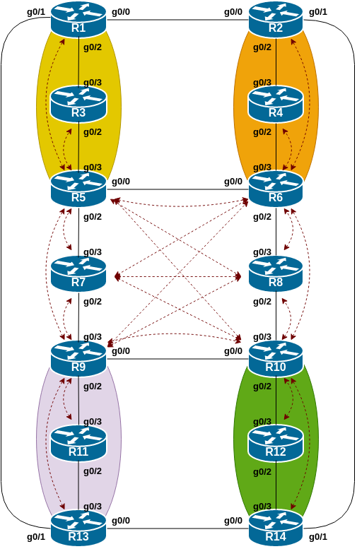
The following common topology is used for the first series of labs.
The colour shaded areas show the four route-reflector clusters we will be setting up. In summary:
| Router Number | Cluster Number | Function |
|---|---|---|
| Router5 | Cluster 1 | Route Reflector for Router1 and Router3 |
| Router6 | Cluster 2 | Route Reflector for Router2 and Router4 |
| Router9 | Cluster 2 | Route Reflector for Router11 and Router13 |
| Router10 | Cluster 4 | Route Reflector for Router12 and Router14 |
Recall from the presentation that IBGP speaking routers need to be fully meshed. The Route Reflector Cluster setup helps network operators scale IBGP so that we can run backbone network infrastructure with hundreds if not thousands of routers.
Even though we have created 4 clusters in the network, the routers which are NOT Route Reflector Clients still need a full mesh IBGP with each other. This means that the Route Reflectors and the standard BGP speaking routers all need to be part of the full mesh. In this case, Router5, Router6, Router7, Router8, Router9 and Router10 all need to be part of the full IBGP mesh.
It is important not to forget to do this otherwise there will appear to be connectivity holes across the IBGP.
Before we start setting up the IBGP sessions and the Route Reflector Clusters, we need to initialise BGP on all the routers in our autonomous system, changing the Cisco defaults to those which are considered industry best practices.
These changes will enable multi-protocol BGP, set metric calculation to be deterministic1, and fix the BGP default protocol distance so that it is much higher (i.e. less important) than any other routing protocol2.
Also note that Cisco IOS assumes that all peers will exchange IPv4 prefixes even if the peering is set up to use another IP protocol - of course this makes no sense, so we will turn off that assumption too by using the no bgp default ipv4-unicast command.
router bgp 64500
 bgp log-neighbor-changes
 bgp deterministic-med
 no bgp default ipv4-unicast
!
 address-family ipv4
  distance bgp 200 200 200
!
 address-family ipv6
  distance bgp 200 200 200
!
As was discussed in the presentation, IBGP sessions are set up between the Loopback interfaces of the IBGP speakers. To do this we use the update-source Loopback 0 configuration, which then uses the IP address of the Loopback interface for the IBGP session.
We will also set up a password on the IBGP session - in this case we will use BGP-PW.
Please note these two details for the specific sections following.
The following steps apply to the routers in the core of the network. Referring to the topology diagram above, these are Router5, Router6, Router7, Router8, Router9 and Router10. Each of these routers will have 5 neighbours in the full mesh.
We will now create our Peer-Group for the Core IBGP mesh. Here is what the configuration template would look like:
router bgp 64500
 address-family ipv4
  neighbor core-v4ibgp peer-group
  neighbor core-v4ibgp remote-as 64500
  neighbor core-v4ibgp description IBGP for Core mesh
  neighbor core-v4ibgp update-source loopback 0
  neighbor core-v4ibgp password BGP-PW
!
 address-family ipv6
  neighbor core-v6ibgp peer-group
  neighbor core-v6ibgp remote-as 64500
  neighbor core-v6ibgp description IBGP for Core mesh
  neighbor core-v6ibgp update-source loopback 0
  neighbor core-v6ibgp password BGP-PW
!
Next we have to apply the Peer Group to the neighbours. Here is what the configuration template would look like:
router bgp 64500
 address-family ipv4
  neighbor <IBGPv4> peer-group core-v4ibgp
  neighbor <IBGPv4> description IBGP with RouterA
  neighbor <IBGPv4> activate
!
 address-family ipv6
  neighbor <IBGPv6> peer-group core-v6ibgp
  neighbor <IBGPv6> description IBGP with RouterA
  neighbor <IBGPv6> activate
!
For the lab routers, replace <IBGPv4> with the IPv4 address of the Loopback interface of the IBGP neighbour, and <IBGPv6> with the IPv6 address of the Loopback interface of the IBGP neighbour. Do this for all the routers taking part in the core mesh. Don’t forget to update the description as well!
Once completed, each router in the core IBGP should have a standard IBGP session with 5 other routers. The show ip bgp neighbor and show bgp ipv6 unicast neighbor commands should show 5 neighbours in each case.
If you don’t see 5 neighbours for IPv4 or for IPv6, it is important that you work out why.
If any IBGP session is down, also work out why - it might just be that the team working on that router aren’t as quick as you have been. But check why the IBGP session is down - they may be also thinking the same about you.
Hint: IBGP sessions configured but are still down could be because the password used is incorrect. Check the router logs by running show logging at the command prompt.
The following steps apply to just the routers which will be acting as the Route Reflectors in our network. These routers are Router5, Router6, Router9 and Router10. Do not apply the configuration noted below to any other router, as it is very specific to the Route Reflectors only.
Following standard industry practice, we will originate the aggregate address blocks used in the lab from the Route Reflectors.
(We could also originate from the Route Reflector Clients and the other IBGP speaking routers if we wanted to, but most network operators will originate their aggregates from their core routers, which are typically operated as Route Reflectors.)
router bgp 64500
 address-family ipv4
  network 100.68.0.0 mask 255.255.240.0
!
 address-family ipv6
  network 2001:DB8::/32
!
ip route 100.68.0.0 255.255.240.0 Null0
ipv6 route 2001:DB8::/32 Null0
!
Note that we require a static route for the aggregate pointing to the Null interface. This creates the entry in the Routing Table (Global RIB) which then indicates to BGP that the network statement should create the equivalent entry in the BGP table (BGP RIB) so that the prefix can be propagated by BGP.
As you will recall from the IS-IS lab, Router6 hosts the transit link to the outside world. As you will recall from the address plan for this lab, the IPv4 address block in use for our infrastructure is 100.68.0.0/20, and the IPv6 address block in use is 2001:DB8::/32.
The infrastructure on the outside of Router6 uses IPv4 addresses from the 100.64.0.0/22 address block and so is reachable by the IS-IS default route we have originated in the previous lab from Router6.
But we have borrowed a /64 subnet out of 2001:DB8::/32 for IPv6, so we need to announce this /64 by IBGP internally in our lab. Router6 will do this now, using the following configuration:
router bgp 64500
 address-family ipv6
  network 2001:DB8::/64
!
The interface GigabitEthernet0/1 is configured with this /64 subnet, hence creating the matching RIB entry, so BGP will then announce the prefix to the other routers in AS64500.
Question: we could have announced this route using IS-IS - how would we have done that?
Answer: we would have marked GigabitEthernet0/1 as a passive interface under the IS-IS configuration. However, that is injecting an external address into our IGP and our preference, as we learned from the BGP presentations, is to carry external addresses in BGP. Which is why we have used BGP here.
We will now set up the IBGP sessions from the Route Reflectors to their Clients.
The specific configuration that differentiates an IBGP session with a Router Reflector Client over a standard IBGP session is the use of the route-reflector-client keyword.
Here is what the configuration would look like for an IBGP session from a Route Reflector with RouterA as a client. First we create the Peer Group:
router bgp 64500
 address-family ipv4
  neighbor rr-v4client peer-group
  neighbor rr-v4client remote-as 64500
  neighbor rr-v4client description IBGP with RR Client
  neighbor rr-v4client update-source loopback 0
  neighbor rr-v4client password BGP-PW
  neighbor rr-v4client route-reflector-client
!
 address-family ipv6
  neighbor rr-v6client peer-group
  neighbor rr-v6client remote-as 64500
  neighbor rr-v6client description IBGP with RR Client
  neighbor rr-v6client update-source loopback 0
  neighbor rr-v6client password BGP-PW
  neighbor rr-v6client route-reflector-client
!
And then we set up the peerings with the clients using the Peer Group we created:
router bgp 64500
 address-family ipv4
  neighbor <clientA-v4> peer-group rr-v4client
  neighbor <clientA-v4> description IBGP with ClientA
  neighbor <clientA-v4> activate
 address-family ipv6
  neighbor <clientA-v6> peer-group rr-v4client
  neighbor <clientA-v6> description IBGP with ClientA
  neighbor <clientA-v6> activate
!
For the lab routers, replace <clientA-v4> with the IPv4 address of the Loopback interface of RouterA, and <clientA-v6> with the IPv6 address of the Loopback interface of RouterA. Don’t forget to update the description as well!
Each Route Reflector has two clients, so use the above configuration to construct the required configuration on the Route Reflectors.
The following steps only apply to the Route Reflector Clients, namely Router1, Router2, Router3, Router4, Router11, Router12, Router13 and Router14.
The Route Reflector Clients only have one IBGP session, and that is with their Route Reflector. Please do not configure IBGP from the Client to any other router apart from its Reflector.
Here is what the configuration would look like for an IBGP session from a Route Reflector Client to its Route Reflector. First we create the Peer Group:
router bgp 64500
 address-family ipv4
  neighbor rr-v4 peer-group
  neighbor rr-v4 remote-as 64500
  neighbor rr-v4 description IBGP with Route Reflector
  neighbor rr-v4 update-source loopback 0
  neighbor rr-v4 password BGP-PW
!
 address-family ipv6
  neighbor rr-v6 peer-group
  neighbor rr-v6 remote-as 64500
  neighbor rr-v6 description IBGP with Route Reflector
  neighbor rr-v6 update-source loopback 0
  neighbor rr-v6 password BGP-PW
!
And then we set up the peerings with the clients using the Peer Group we created:
router bgp 64500
 address-family ipv4
  neighbor <reflectorA-v4> peer-group rr-v4
  neighbor <reflectorA-v4> description IBGP with ReflectorA
  neighbor <refelctorAv4> activate
 address-family ipv6
  neighbor <reflectorA-v6> peer-group rr-v4
  neighbor <reflectorA-v6> description IBGP with ReflectorA
  neighbor <reflectorA-v6> activate
!
For the lab routers, replace <reflectorA-v4> with the IPv4 address of the Loopback interface of the Route Reflector, and <reflectorA-v6> with the IPv6 address of the Loopback interface of Route Reflector. Don’t forget to update the description as well!
Once the IBGP configuration steps above have been completed, each team should check how many IBGP sessions they see on their router.
show ip bgp summary will list all the IPv4 neighbours, and show bgp ipv6 unicast summary will list all the IPv6 neighbours:
The Route Reflector Clients should have just one IBGP neighbour for each of IPv4 and IPv6 - their Route Reflector.
Router7 and Router8 should have 5 neighbours each for IPv4 and IPv6.
The Route Reflectors will have a total of 7 neighbours for each protocol: two of them will be their Clients, and the other 5 will be the core IBGP mesh.
If this is not what is seen, then it is time to troubleshoot to see why there might be a missing neighbour, or why there are too many neighbours, or why a BGP session might be down.
Note: more modern versions of Cisco IOS support the command show bgp all summary which shows the neighbours in all address families configured on the router.
Hint: If an IBGP session is present but not active, verify that the peer address is correct, and that the password used the BGP session is correct. Check the router logs by running show logging - if you see messages like:
%TCP-6-BADAUTH: No MD5 digest from 100.68.0.1(179) to 100.68.0.2(26557) (RST)
%TCP-6-BADAUTH: No MD5 digest from 100.68.0.1(179) to 100.68.0.2(26557) (RST)
%TCP-6-BADAUTH: No MD5 digest from 100.68.0.1(179) to 100.68.0.2(26557) (RST)
then this is caused by a missing password on one side of the BGP session. If you see messages like:
%TCP-6-BADAUTH: Invalid digest from 100.68.0.1(179) to 100.68.0.2(26557) (RST)
%TCP-6-BADAUTH: Invalid digest from 100.68.0.1(179) to 100.68.0.2(26557) (RST)
%TCP-6-BADAUTH: Invalid digest from 100.68.0.1(179) to 100.68.0.2(26557) (RST)
then there is a misconfigured password - and its best to start again at both ends of the BGP session rather than arguing with the neighbour about who got the password wrong.
This diagram shows the IBGP mesh that should be in place at this stage of the lab. The red dotted lines show the IBGP sessions. Compare the diagram with the IBGP sessions configured on each router.
We are now going to add a “customer” route into BGP on each router. We don’t have any “customers” as such connected to our routers in the lab, so we are going to simulate the connectivity by simply using a Null0 interface as the destination of the “customer” route.
Refer to the address plan to find the customer subnet to be used for each router in the lab.
Each team should now set up a static route pointing to the Null0 interface for the customer subnet that they are to originate. Once the static route is set up, the team should then add an entry into the BGP table.
Here is an example showing what Router11 might configure:
ip route 100.68.2.128 255.255.255.192 Null0
ipv6 route 2001:DB8:B::/48 Null0
!
router bgp 64500
 address-family ipv4
  network 100.68.2.128 mask 255.255.255.192
!
 address-family ipv6
  network 2001:DB8:B::/48
!
Once the setup has been completed, we will check several aspects of the work we have done.
We will look at the state of the BGP table (for IPv4 and IPv6) as well as check our Route Reflector output, and the impact of the deployment of Peer Groups.
First of all, we need to check the BGP table.
Are there routes seen via show ip bgp and show bgp ipv6 unicast? If not, why not?
Once every team in the class has done their configuration, each team should see the IPv4 and IPv6 aggregates as well as the fourteen IPv4 /26s and IPv6 /48s introduced in the previous step.
If this is not happening, work with your neighbours to fix the problem.
Here is an example of the IPv4 BGP table as seen from Router14:
Router14#sh ip bgp
BGP table version is 16, local router ID is 100.68.15.254
Status codes: s suppressed, d damped, h history, * valid, > best, i - internal,
              r RIB-failure, S Stale, m multipath, b backup-path, f RT-Filter,
              x best-external, a additional-path, c RIB-compressed,
              t secondary path,
Origin codes: i - IGP, e - EGP, ? - incomplete
RPKI validation codes: V valid, I invalid, N Not found

     Network          Next Hop            Metric LocPrf Weight Path
 *>i  100.68.0.0/26    100.68.15.241            0    100      0 i
 *>i  100.68.0.0/20    100.68.15.250            0    100      0 i
 *>i  100.68.0.64/26   100.68.15.242            0    100      0 i
 *>i  100.68.0.128/26  100.68.15.243            0    100      0 i
 *>i  100.68.0.192/26  100.68.15.244            0    100      0 i
 *>i  100.68.1.0/26    100.68.15.245            0    100      0 i
 *>i  100.68.1.64/26   100.68.15.246            0    100      0 i
 *>i  100.68.1.128/26  100.68.15.247            0    100      0 i
 *>i  100.68.1.192/26  100.68.15.248            0    100      0 i
 *>i  100.68.2.0/26    100.68.15.249            0    100      0 i
 *>i  100.68.2.64/26   100.68.15.250            0    100      0 i
 *>i  100.68.2.128/26  100.68.15.251            0    100      0 i
 *>i  100.68.2.192/26  100.68.15.252            0    100      0 i
 *>i  100.68.3.0/26    100.68.15.253            0    100      0 i
 *>   100.68.3.64/26   0.0.0.0                  0         32768 i
Router14#
The instructors will demonstrate the BGP table to the class - it should look the same as above!
If you go to one of the route reflector clients, what do you notice about the routes learned on the router?
Hopefully you will see a Cluster list noted along side the prefix - this is the list of route-reflectors that the prefix has been passed through, and is the way a route-reflector avoids routing loops in the IBGP mesh.
Let’s now look at one of the routes - here is the BGP table entry for the route originated by Router1:
Router14#sh ip bgp 100.68.0.0/26
BGP routing table entry for 100.68.0.0/26, version 2
BGP Bestpath: deterministic-med
Paths: (1 available, best #1, table default)
  Not advertised to any peer
  Refresh Epoch 2
  Local
    100.68.15.241 (metric 4) from 100.68.15.250 (100.68.15.250)
      Origin IGP, metric 0, localpref 100, valid, internal, best
      Originator: 100.68.15.241, Cluster list: 100.68.15.250, 100.68.15.245
      rx pathid: 0, tx pathid: 0x0
Router14#
Do you notice the Originator and the Cluster list in the output above?
Originator is the router ID of the router which introduce the prefix into the IBGP mesh - this is Router1. And the Cluster list shows the list of Router Reflectors the prefix has been reflected through: Router1 sends it to Router5 (100.68.15.245) and Router5 has sent it to Router10 (100.68.15.250) which has then sent it on to Router14, giving the output above.
Check other paths on your router - and check for IPv6 as well; you should see similar results.
Finally we will check the BGP Peer Groups. What do you see if you do the show ip bgp peer-group command on any router?
The Route Reflector Clients will report on their Peer Group used to talk to the Reflector - here is an example for the IPv4 portion for Router1:
Router1>sh ip bgp peer-group
BGP peer-group is rrv4,  remote AS 64500
 Description: IBGP with Route Reflector
  BGP version 4
  Neighbor sessions:
    0 active, is not multisession capable (disabled)
  Do log neighbor state changes (via global configuration)
  Default minimum time between advertisement runs is 0 seconds

 For address family: IPv4 Unicast
  BGP neighbor is rrv4, peer-group internal, members:
  100.68.15.245
  Index 0, Advertise bit 0
  Update messages formatted 0, replicated 0
  Number of NLRIs in the update sent: max 0, min 0
Note the single member of the Peer Group - Router5 (the Route Reflector).
Now let’s go to any of the Route Reflectors - here is an example from Router6 (again showing only the IPv4 output):
Router6#sh ip bgp peer-group
BGP peer-group is rr-v4client,  remote AS 64500
 Description: IBGP with RR Client
  BGP version 4
  Neighbor sessions:
    0 active, is not multisession capable (disabled)
  Do log neighbor state changes (via global configuration)
  Default minimum time between advertisement runs is 0 seconds

 For address family: IPv4 Unicast
  BGP neighbor is rr-v4client, peer-group internal, members:
  100.68.15.242 100.68.15.244
  Index 0, Advertise bit 0
  Route-Reflector Client
  Update messages formatted 0, replicated 0
  Number of NLRIs in the update sent: max 0, min 0

<snip>

BGP peer-group is core-v4ibgp,  remote AS 64500
 Description: IBGP for Core mesh
  BGP version 4
  Neighbor sessions:
    0 active, is not multisession capable (disabled)
  Do log neighbor state changes (via global configuration)
  Default minimum time between advertisement runs is 0 seconds

 For address family: IPv4 Unicast
  BGP neighbor is core-v4ibgp, peer-group internal, members:
  100.68.15.245 100.68.15.247 100.68.15.248 100.68.15.249 100.68.15.250
  Index 0, Advertise bit 0
  Update messages formatted 0, replicated 0

<snip>
The first section covers the members of rr-v4client (Router2 and Router4) and the second section covers the members of core-v4ibgp (Router5 to Router10).
Now run the command show ip bgp update-group. As you will have seen in the presentation, this is Cisco IOS internal coding to combine outbound updates for groups of peers it considers have the same outbound policy - which is why we use Peer Groups today for tidiness and readability of the configuration code.
Router6#sh ip bgp update-group
BGP version 4 update-group 1, internal, Address Family: IPv4 Unicast
  BGP Update version : 40/0, messages 0, active RGs: 1
  Route-Reflector Client
  Topology: global, highest version: 40, tail marker: 40
  Format state: Current working (OK, last not in list)
                Refresh blocked (not in list, last not in list)
  Update messages formatted 36, replicated 69, current 0, refresh 0, limit 1000
  Number of NLRIs in the update sent: max 2, min 0
  Minimum time between advertisement runs is 0 seconds
  Has 2 members:
   100.68.15.242    100.68.15.244

BGP version 4 update-group 2, internal, Address Family: IPv4 Unicast
  BGP Update version : 40/0, messages 0, active RGs: 1
  Topology: global, highest version: 40, tail marker: 40
  Format state: Current working (OK, last not in list)
                Refresh blocked (not in list, last not in list)
  Update messages formatted 31, replicated 35, current 0, refresh 0, limit 1000
  Number of NLRIs in the update sent: max 2, min 0
  Minimum time between advertisement runs is 0 seconds
  Has 5 members:
   100.68.15.245    100.68.15.247    100.68.15.248    100.68.15.249
   100.68.15.250
Question: What are the advantages of using peer-groups?
Answer: BGP peer groups allow a common configuration to be used for several BGP peers. The most common application is for IBGP. All internal BGP peers in an ISP network tend to have the same relationship with each other. Rather than having a substantial configuration per peer, and having to change every peering when details need to be changed, the configuration can be put in a peer-group, and only the peer group has to be changed to alter the peering configuration for all IBGP peers. This substantially reduces the work overhead required in making changes, and significantly cleans up the configuration for the operator to manage and view.
It is strongly recommended that the peer-group subcommand be the “default” way of configuring all BGP peers. As was stated before, most IBGP peers have the same configuration, so it is of great benefit to the operations staff, and network engineering staff, to simplify the configurations wherever possible. Besides, a configuration which makes extensive use of peer-groups is usually much easier to read than one which has distinct configuration per peer, especially in networks with large numbers of peers.
Note: Wherever BGP is configured in future in the workshop, it is expected that peer-groups will be used as part of the BGP configuration (and most definitely for any IBGP configuration).
What IOS show command(s) will display the router’s IPv4 BGP route table?
What IOS show command(s) will display the router’s IPv6 BGP route table?
Why do we change the EBGP distance from the default 20 to 200?
Why is the static pull up route necessary in relation to inserting a prefix into IBGP?
Please consult the BGP Attributes presentation for background on what “Deterministic MED” is and why it is important to set it.↩
Cisco’s default protocol distance for EBGP is 20, lower than the protocol distance for OSPF and IS-IS (110 and 115 respectively). This poses serious risks should prefixes used inside the network be received externally by EBGP (and evade any BGP prefix filtering in place). Therefore we change the EBGP protocol distance to be the same as for IBGP, namely 200.↩