The purpose of this lab is to set up the necessary infrastructure ready to deploy routing protocols being explored in this workshop. The basic physical lab will be created, with IP addressing and essential router configuration so that the router has basic operational best practice configuration in place.
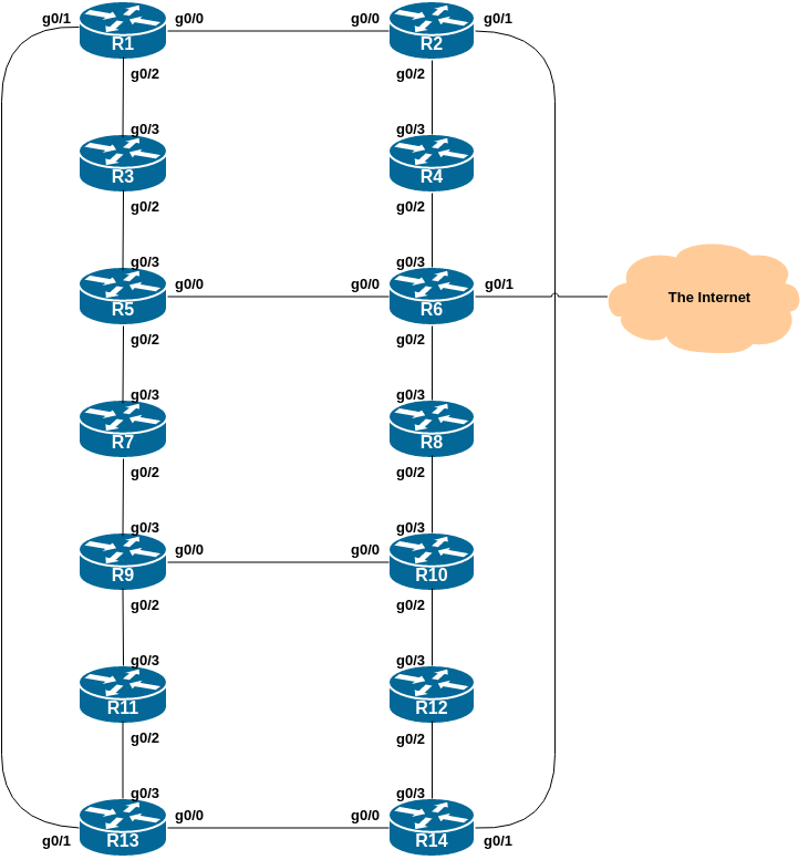
The initial lab topology sets up 14 routers interconnected with each as per the diagram shown below.
The lab will start simply by configuring each router, setting up the basic configuration according to current best practices. The address plan for the entire network is described in the Address Plan document. The initial set up is shown below.
Each participant will be assigned to a router. Depending on the number of participants, either a one or two participants will be responsible for the configuration of a router. You may be asked to rotate and work on a different router so that you have the opportunity to understand the network from another point of view.
As you go through the exercises, you will see examples of configurations for one or more routers. Make sure to take those examples and adapt them to your own router, network topology and addressing scheme. Use the diagrams to guide you.
Refer to the Lab Access Instructions document for information about logging into the routers that have been assigned to you.
Refer to the IP Address Plan document for information about the IP address plan for the network infrastructure for these labs.
The following configuration examples show the suggested/recommended configuration to be implemented on the routers in each group.
Replace the X in the examples with the actual router number in use, as appropriate.
Router> enable
Router# config terminal
Enter configuration commands, one per line. End with CNTL/Z.
Router(config)# hostname RouterX
RouterX(config)#
Notice how the default Router(config)# prompt changes to include the hostname of the device.
The rest of the configuration examples throughout these workshop lab notes assume you are in configuration mode (unless otherwise stated).
There is no DNS resolver at this stage of the lab set up, so we stop the router from trying to do domain name resolution for any encountered addresses.
no ip domain-lookup
Even though there is currently no connectivity to access a DNS resolver, we will still configure the lab’s domain name as we will need this when we set up Secure Shell.
ip domain name ws.nsrc.org
By default, Cisco devices will try all transports available if they don’t recognise what is typed into the command line. This behaviour is annoying especially if making a typo during configuration work, so we will disable the behaviour completely. We will also set the idle-timeout on the console and other ports to 30 minutes - after 30 minutes of no activity on the port, the device will disconnect the connection.
line con 0
  transport preferred none
  exec-timeout 30 0
!
line aux 0
  transport preferred none
  exec-timeout 30 0
!
line vty 0 4
  transport preferred none
  exec-timeout 30 0
!
Note the ! in the configuration snippet above - Cisco IOS uses this as a “comment” line or a separator to space the configuration out to make each section more “readable”. You will see the ! used in the examples throughout the lab notes. There is no need to type it in when you see it in these examples, as it does nothing.
We will need to change the escape sequence for the console and vtys from the default value of CTRL ^ because that sequence isn’t transmitted by the web interface we use to access the router consoles. Instead we will use CTRL C whch is ASCII 3.
line con 0
 escape-character 3
line aux 0
 escape-character 3
line vty 0 4
 escape-character 3
!
We will use the username isplab for this workshop. It is a role account, note, something that is strongly discouraged on public infrastructure. However, we use it here only for ease of operating the lab, and that we will need to connect to other groups’ routers through the duration of this workshop.
Recent Cisco IOS (and IOS-XE) software is starting to deprecate the type 5 encryption which has been Cisco’s standard since the mid 1990s. Cisco has introduced a new type 9 encryption (using the scrypt hashing algorithm1), and we will use that on our switches as they support this. Newer software platforms use type 9 by default.
username isplab algorithm-type scrypt secret lab-PW
!
enable algorithm-type scrypt secret lab-EN
!
service password-encryption
!
The default authentication model used in Cisco’s IOS is from the late 80s and is really very obsolete. We will instead use Cisco’s implementation of AAA, first introduced in around 1995. The code snippet below uses the locally configured username/password pair for standard login, with the locally configured enable secret to go into configuration mode.
aaa new-model
aaa authentication login default local
aaa authentication enable default enable
!
Don’t be fooled by the new-model name - it’s not new! This has been around since 1995 and should be treated as a lesson in how not to name keywords in code!
No logs are to be sent to the console. Instead they are sent to a log buffer. To access the logs in the log buffer, use the command show logging.
no logging console
logging buffered 8192 debugging
And we also want to set up improved time-stamping for the log messages as well:
service timestamps debug datetime msec localtime show-timezone year
service timestamps log datetime msec localtime show-timezone year
Turn on IPv6 Routing (not on by default in many versions of Cisco IOS)
ipv6 unicast-routing
no ip source-route
no ipv6 source-route
Some Cisco IOS/IOS-XE images ship with the built-in web server turned on. This is a major security risk, so we turn it off.
no ip http server
no ip http secure-server
Some images will have this turned off already, but we include the configuration in our “best practice” initialisation template anyway.
Enable Path MTU Discovery on the router - this is not enabled by default for connections to the control plane (but it is enabled by default now for BGP).
ip tcp path-mtu-discovery
Depending on which environment is used, you will find that your switch might have a default login banner already set. We will modify this so that it is a bit more informative:
banner login ^
           BGP Deployment Workshop Lab
         Network Startup Resource Center
^
Note the ^ symbol - this is used as the marker for the start and end of the banner text.
This banner will notify administrators every time they connect to the device. In real life, we’d also include wording about authorised access, authorised use, and that the device is being monitored.
Cisco IOS also supports other banner types, but we will not use any of those in this lab. They are shown for information below:
RouterX(config)#banner ?
  LINE            c banner-text c, where 'c' is a delimiting character
  config-save     Set message for saving configuration
  exec            Set EXEC process creation banner
  incoming        Set incoming terminal line banner
  login           Set login banner
  motd            Set Message of the Day banner
  prompt-timeout  Set Message for login authentication timeout
  slip-ppp        Set Message for SLIP/PPP
The use of telnet is considered obsolete given that everything is sent in the clear when communicating with other devices. This includes passwords and other confidential information.
Cisco devices have telnet enabled by default. We are going to disable telnet and configure the routers to use ssh instead. We already created the domain name earlier, so we can now generate the SSH key pairs for the device:
crypto key generate rsa modulus 2048We will use a modulus of 2048 - key sizes supported are 360 to 4096, and a modulus of at least 768 is the minimum for SSH version 2. In real life, we’d probably make the modulus 4096.
Next we set the SSH version to be version 2:
ip ssh version 2Finally we enable SSH access to our device (disabling telnet at the same time) by:
line vty 0 4
 transport input ssh
!
Note that Cisco devices by default have all incoming transports activated; if you try:
RouterX(config)#line vty 0 4
RouterX(config-line)#transport input ?
  all     All protocols
  none    No protocols
  pad     X.3 PAD
  rlogin  Unix rlogin protocol
  ssh     TCP/IP SSH protocol
  telnet  TCP/IP Telnet protocol
the device will display the options available. By specifying only ssh, we disable all other incoming transports.
SSHv2 is now configured on the device, and ready to use in future labs.
With the basic configuration in place, save the configuration. To do this, exit from enable mode by typing end or <ctrl>Z, and at the command prompt enter write memory. If you are prompted [confirm] hit enter again.
RouterX(config)# end
RouterX# write memory
Warning: Attempting to overwrite an NVRAM configuration previously written
by a different version of the system image.
Overwrite the previous NVRAM configuration?[confirm]
Building configuration...
[OK]
RouterX#
It is highly recommended that the configuration is saved quite frequently to NVRAM. If the configuration is not saved to NVRAM, any changes made to the running configuration will be lost after a power cycle or virtual machine failure.
Log off the router:
RouterX# exitand then log back in again. Notice how the login sequence has changed, prompting for a username and password from the user, like this:
RouterX con0 is now available

Press RETURN to get started.

User Access Verification

Username:
Note that at each checkpoint in the workshop, you should save the configuration to memory – remember that powering the device off will result in it reverting to the last saved configuration in NVRAM.
Before we start with the interface configuration we need to become familiar with the address plan for the workshop lab.
As noted earlier, please refer to the IP Address Plan document for information about the IP address plan for the network infrastructure for these labs.
This lab introduces the basic concepts of putting together a sensible addressing plan for a Service Provider backbone. We are building one autonomous system out of the 14 routers we have in the lab.
We will assume for the purposes of this lab that our network is using an IPv4 /20. Rather than using public address space, we are going to use a portion of 100.64.0.0/10 (the IPv4 Shared Address block) for this lab, 100.68.0.0/20. In the real world Internet, we would use public address space for our network infrastructure.
The typical way that network operators split up their allocated address space is to carve it into three pieces. One piece is used for assignments to customers, the second piece is used for infrastructure point-to-point links, and the final piece is used for loopback interface addresses for all their backbone routers. The following diagram shows how this might be done for IPv4:
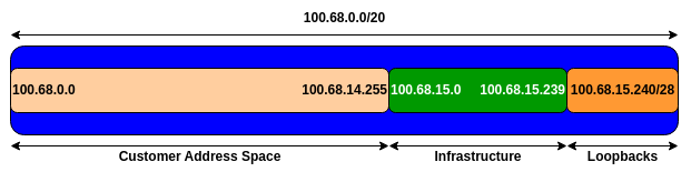
Study the IP Address Plan document. Notice how the infrastructure addressing starts at 100.68.15.0 and carries on up to 100.68.15.35 – this leave us room to grow the network by more point-to-point links, up to 100.68.15.239 in fact. Notice how we have set aside just a single /28 for the router loopbacks – but we have only used the 14 addresses from 241 up to 254 for our network (leaving 240 and 255 free for a couple of more routers if we wanted to).
The following diagram shows the equivalent plan for our IPv6 addressing. The Regional Internet Registries distribute IPv6 address space in /32 chunks to network operators – we assume for the purposes of this lab that our operator has received a /32. Rather than using public address space, we are going to use 2001:DB8::/32, the IPv6 Documentation Address block. In the real world Internet, we would use public address space for our network infrastructure.
The typical way that network operators split up their allocated address space is to carve it into three pieces. One piece is used for assignments to customers, the second piece is used for infrastructure point-to-point links, and the final piece is used for loopback interface addresses for all their backbone routers. For IPv6, we reserve an entire /48 out of this /32 for our network infrastructure - and in this lab we are reserving 2001:DB8:0::/48 (purposely including the 0 to show the /48 we are using). The following 2001:DB8:1::/48 all the way up to 2001:DB8:FFFF::/48 are free for assignments to end-users and other activities. The following diagram shows what we are doing for IPv6:
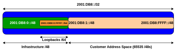
Study the IP Address Plan document. Notice how the infrastructure addressing uses the first /48 out of the /32 address block. Notice how we have set aside one /64 out of the infrastructure block for the router loopbacks.
Each router has a connection to either two or three other routers, depending on where they are in the topology. Configure your interfaces according to the diagram and the supplied address plan.
Notice that we address IPv4 point-to-point links with a /31 (common practice on most router platforms today), and IPv6 point-to-point links with a /127.
The example below shows the configuration used on the interfaces connecting Router1 and Router2.
Router1:
interface GigabitEthernet0/0
 description P2P Ethernet Link to Router2
 ip address 100.68.15.0 255.255.255.254
 no ip redirects
 no ip proxy-arp
 ipv6 address 2001:DB8:0:1::0/127
 ipv6 nd prefix default no-advertise
 ipv6 nd ra suppress all
 load-interval 30
 no shutdown
!
Router2:
interface GigabitEthernet0/0
 description P2P Ethernet Link to Router1
 ip address 100.68.15.1 255.255.255.254
 no ip redirects
 no ip proxy-arp
 ipv6 address 2001:DB8:0:1::1/127
 ipv6 nd prefix default no-advertise
 ipv6 nd ra suppress all
 load-interval 30
 no shutdown
!
Consult the address plan and set up the addresses correctly for the interfaces connecting your router to your neighbours.
Proxy ARP is the technique in which one host, usually a router, answers ARP requests intended for another machine. By “faking” its identity, the router accepts responsibility for routing packets to the “real” destination. Proxy ARP can help machines on a subnet reach remote subnets without the need to configure routing or a default gateway.
Disadvantages of proxy arp:
It increases the impact of ARP spoofing, in which a machine claims to be another in order to intercept packets.
It hides network misconfigurations in hosts
Hosts will have larger ARP tables
ICMP redirects can be sent to a host when the router knows that another router in the same subnet has a better path to a destination. If a hacker installs a router in the network that causes the legitimate router to learn these ilegitimate paths, the hacker’s router will end up diverting legitimate traffic thanks to ICMP redirects. Thus, we recommend that you disable this feature in all your interfaces.
IPv6 router advertisements are sent periodically by routers to inform hosts that the router is present, and to allow hosts to autoconfigure themselves using stateless autoconfiguration mechanisms. This is not necessary on point-to-point interfaces.
This prevents the router from sending any prefixes as part of router advertisements, so the client will not auto-configure itself with a global IPv6 address. This is helpful for IOS versions where you cannot suppress solicited RA messages.
The Cisco IOS default interface load that is displayed in the show interface command is measured over 5 minutes. Most operators reduce this averaging to be over 30 seconds. Here is typical output from running the show interface command after the load interface is changed to 30 seconds:
Router# show interface gig 0/0
...
  30 second input rate 0 bits/sec, 0 packets/sec
  30 second output rate 0 bits/sec, 0 packets/sec
...
Also create a Loopback interface and apply the IPv4 and IPv6 addresses to it - consult the address plan for the addresses used for each router. We will be using the Loopback interface later in the labs for both the IGP and for BGP configuration.
Here is an example of the configuration that might be used on Router6. Remember that the IPv4 address on the Loopback is a /32 and the IPv6 address on the Loopback is /128.
interface Loopback0
 description Loopback on Router6
 ip address 100.68.15.246 255.255.255.255
 ipv6 address 2001:DB8:0:FFFF::6/128
!
We also need to modify the configuration of the Null interface to improve our infrastructure security. We will be using the Null interface throughout this lab.
Industry best practice today is to route address blocks in use by any autonomous system to the Null interface, so that looping traffic (packet ping-pong) for unreachable destinations within the address block is avoided. So that the Null doesn’t become a target for denial of service attacks, we need to add configuration so that the Null interface does not send any ICMP unreachable messages. Like this:
interface Null0
 no ip unreachables
 no ipv6 unreachables
!
The network has a transit link, available from Router6. This allows us to do traceroutes and other connectivity tests from the lab network out to the world. The group operating Router6 will now enable this transit connectivity. The other groups should proceed to the last section of this lab.
The transit link is on interface GigabitEthernet 0/1 of Router6. Here is the additional configuration required:
interface GigabitEthernet0/1
 description Link to the World
 ip address 100.64.0.254 255.255.252.0
 ipv6 address FE80::254 link-local
 ipv6 address 2001:DB8::254/64
!
Notice that we are specifying a link-local address for the IPv6 address on this interface. When you check the interface status for IPv6 you should see something like this:
Router6#sh ipv6 int gig 0/1
GigabitEthernet0/1 is up, line protocol is up
  IPv6 is enabled, link-local address is FE80::254
  No Virtual link-local address(es):
  Description: Link to the World
  Global unicast address(es):
    2001:DB8::254, subnet is 2001:DB8::/64
<snip>
Once the interface is configured, test that it works by pinging 100.64.0.1 and FE80::1 which are the IPv4 and IPv6 default gateways respectively.
Here is an example from an earlier workshop for IPv4:
Router6#ping 100.64.0.1
Type escape sequence to abort.
Sending 5, 100-byte ICMP Echos to 100.64.0.1, timeout is 2 seconds:
!!!!!
Success rate is 100 percent (5/5), round-trip min/avg/max = 1/1/1 ms
Router6#
And for IPv6:
Router6#ping fe80::1 source GigabitEthernet0/1
Output Interface: GigabitEthernet0/1
Type escape sequence to abort.
Sending 5, 100-byte ICMP Echos to FE80::1, timeout is 2 seconds:
Packet sent with a source address of FE80::254%GigabitEthernet0/1
!!!!!
Success rate is 100 percent (5/5), round-trip min/avg/max = 1/1/1 ms
Router6#
If the ping is successful we can now add in default routes for IPv4 and IPv6:
ip route 0.0.0.0 0.0.0.0 100.64.0.1
ipv6 route ::/0 GigabitEthernet0/1 FE80::1
Note that the default route for IPv6 needs to include the interface - the link-local address is local to the link, so we need to specify which link to use (Router6 has 4 active interfaces)!
Test the IPv4 connectivity using traceroute - try tracing to Google’s public DNS resolver. Here is an example from an earlier version of this workshop (for IPv4):
Router6#trace 8.8.8.8
Type escape sequence to abort.
Tracing the route to 8.8.8.8
VRF info: (vrf in name/id, vrf out name/id)
  1 100.64.0.1 0 msec 0 msec 0 msec
  2 192.168.1.254 1 msec 1 msec 1 msec
  3 10.20.26.121 8 msec 8 msec 7 msec
  4 60.240.241.194 [MPLS: Label 24311 Exp 0] 22 msec 22 msec 20 msec
  5 203.26.22.57 [MPLS: Label 24366 Exp 0] 20 msec 21 msec 21 msec
  6 203.221.3.17 20 msec 20 msec
    203.221.3.81 21 msec
  7 72.14.197.162 20 msec 19 msec 20 msec
  8  *  *  *
  9 209.85.253.180 20 msec
    209.85.253.176 20 msec
    8.8.8.8 20 msec
and here is the equivalent for IPv6:
Router6#trace 2001:4860:4860::8888
Type escape sequence to abort.
Tracing the route to 2001:4860:4860::8888

  1 2001:44B8:2134:800:205:1BFF:FEC0:D8AD 0 msec 0 msec 0 msec
  2 2001:44B8:2134:800::FFFF 1 msec 1 msec 1 msec
  3 2407:8800:A000::259 8 msec 8 msec 7 msec
  4 2407:8800:BF00:173:AEC:F5FF:FE27:F289 9 msec 9 msec 9 msec
  5  *  *  *
  6  *
    2407:8800:BF00:7A:232:17FF:FED0:CCE0 20 msec
    2407:8800:BF00:79:232:17FF:FED0:CCE1 20 msec
  7 2001:4860:1:1::6FA 20 msec 21 msec 21 msec
  8 2404:6800:817C::1 21 msec
    2404:6800:805B::1 26 msec 27 msec
  9 2001:4860:4860::8888 19 msec 21 msec 22 msec
All groups should now verify and save the configuration on their routers. Do not forget to do this - if the router is turned off, or rebooted, then any unsaved configuration will be lost.
show running-config
write memory
Do some PING tests on all links to adjacent routers - here is an example for between R5 and R3, R6, and R7:
R5# ping 100.68.15.6         <- R3
R5# ping 2001:DB8:0:4::      <- R3
R5# ping 100.68.15.11        <- R6
R5# ping 2001:DB8:0:6::1     <- R6
R5# ping 100.68.15.13        <- R7
R5# ping 2001:DB8:0:7::1     <- R7
and then verify the output of the following commands:
show arp             : Show ARP cache
show interface       : Show interface state and config
show ip interface    : Show interface IP state and config
show ipv6 neighbors  : Show IPv6 neighbours
show ipv6 interface  : Show interface state and config
show cdp neighbors   : Show neighbours seen via CDP
Can you ping any other routers apart from your directly attached neighbours? If not, why not?
What IP Protocol does Ping and Traceroute use?
Ping the IP address of your neighbour’s router. Look at the time it took for the ping to complete. Now Ping the IP address of your router on the same segment. Look at the time it took to complete a ping. What are the results? Why is there a difference?
IOS also supports the PBKDF2 hashing algorithm, better known as SHA256. This would appear in the saved configuration as “type 8” encryption.↩