
The purpose of this exercise is to look at PortFast, BPDUGuard, CDP, Link State Logging, Link Bundling and DHCP Snooping. We will also shutdown all unused interfaces on our switches. This is a continuation from the VLAN exercise and the lab setup is identical:
It is generally considered a good practice by most campus administrators to shut down unused backbone interfaces on edge, distribution and core switches. Administrators don’t really want users to plug devices into these infrastructure switches - the only connections being made are those by the campus network administrators themselves.
We will now shutdown all unused interfaces on our switches.
For the Core Switch, only interfaces 0/0, 0/1, 0/2 and 0/3 are used in this workshop. So we will shutdown the remainder, using the following commands:
interface range Gi1/0-3,Gi2/0-3,Gi3/0-3
 description Spare
 shutdown
Note that we have included a description saying that the port is spare.
For the Distribution Switch, only interfaces 0/0, 1/0, 1/1 and 2/0 are used in this workshop. We will shutdown the remaining interfaces using these commands:
interface range Gi0/1-3,Gi1/2-3,Gi2/1-3,Gi3/0-3
 description Spare
 shutdown
On the Edge Switch1 in each building, the following ports are unused:
interface range Gi0/2-3,Gi3/0-3
 description Spare
 shutdown
And on the Edge Switch2 in each building, the following ports are unused:
interface range Gi0/1-3,Gi3/0-3
 description Spare
 shutdown
Run the command show interface status and you should see that those ports are now in state “disabled”.
PortFast is a feature that allows end-user stations to be granted instant access to the L2 network. Instead of starting at the bottom of the Blocking-Listening-Learning-Forwarding hierarchy of states (30 seconds!), Portfast starts at the top. The port starts in Forwarding state, and if a loop is detected, STP does all its calculations and blocks the necessary ports. This feature should only be applied to ports that connect end-user stations.
It is common practice these days to configure all end user access ports with portfast to avoid delays in bringing up a link when a device is first connected to the network.
We will configure end-user ports on the Edge switches to be in PortFast mode:
interface range Gi1/0-3,Gi2/0-3
 spanning-tree portfast edge
Alternatively it’s possible to configure all non-trunk ports as portfast, using the global configuration spanning-tree portfast default
With PortFast, end-user ports still participate in STP. That means that anything connected to those ports can send BPDUs and participate in (and affect the status of) the spanning tree calculations. For example, if the device connected to the edge port is configured with a lower bridge priority, it becomes the root switch and the tree topology becomes suboptimal.
Another useful Cisco feature that avoids this situation is BPDUGuard. At the reception of BPDUs, the BPDU guard operation disables the port that has PortFast configured.
BPDUGuard is enabled on all ports with PortFast enabled (Edge switches only!) using the following command:
spanning-tree portfast edge bpduguard defaultThe effect of enabling bpduguard on all ports with portfast enabled is that it is no longer possible to plug in a switch into these ports. This is a useful security device to stop end users from plugging “unauthorised” switches into the campus network.
The switches have CDP (Cisco Discovery Protocol) running by default on all interfaces. You can see the output by running the show cdp neighbor command, and you will see output as in the example below:
edge1-b1-campus1#sh cdp neigh
Capability Codes: R - Router, T - Trans Bridge, B - Source Route Bridge
                  S - Switch, H - Host, I - IGMP, r - Repeater, P - Phone,
                  D - Remote, C - CVTA, M - Two-port Mac Relay

Device ID        Local Intrfce     Holdtme    Capability  Platform  Port ID
dist1-b1-campus1.ws.nsrc.org
                 Gig 0/0           122             R S I            Gig 1/0
dist1-b1-campus1.ws.nsrc.org
                 Gig 0/1           141             R S I            Gig 1/1
CDP is useful for network administrators to find other Cisco devices connected to them and is a useful troubleshooting tool. CDP is proprietary to Cisco - the industry standard is known as LLDP and is supported by most modern switches.
It is advisable to turn off CDP towards end-users. This helps ensuring that end-users don’t gather more information about the network devices than they need to know. We will do this now on the Edge Switches in our campus:
interface range Gi1/0-3,Gi2/0-3
 no cdp enable
and this will turn off CDP towards all the end-users. You will still be able to see the adjacent backbone switches though; confirm this by running the show cdp neighbor command again on each of the 4 edge switches.
Another useful feature found on most switches is the ability to disable link state logging from filling up the switch log files, and thus the log files on the SYSLOG host. End-users come and go, power on and off their devices, and each time this results in a link UP or link DOWN message appearing in SYSLOG. To make SYSLOGs easier to read, we can stop these log messages from being recorded.
Again, we will implement this just on the end-user ports of our edge switches. We want to retain link logging on our backbone infrastructure links so that we are aware of reasons why these may be going up or down via our SYSLOG host.
We will do this now on the Edge Switches in our campus:
interface range Gi1/0-3,Gi2/0-3
 no logging event link-status
and this will turn off link logging on all end-user links.
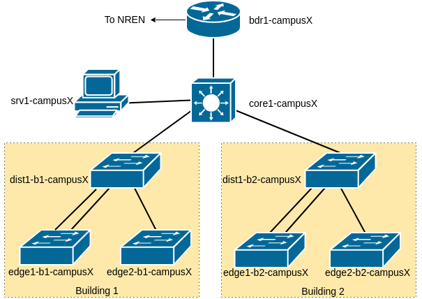
We now want more capacity and link redundancy between the edge switch and distribution switches. The network diagram below shows the second link between the distribution switch and the first edge switch in each building.
Configure a Port Channel between dist1-bY-campusX and edge1-bY-campusX (so, for example, between dist1-b1 and edge1-b1, and between dist1-b2 and edge1-b2, etc). Don’t forget that we need to make the Port Channel interface a trunk port too - the Aggregated Link interface (known as a LAG - Link Aggregation Group) has to be of the same type as the original underlying interfaces.
On dist1-bY-campusX we already have this configuration:
interface Gig 1/0
 description First Link to edge1-bY-campusX
 switchport trunk allowed vlan 10,11,18
 switchport trunk encapsulation dot1q
 switchport mode trunk
!
interface Gig 1/1
 description Second Link to edge1-bY-campusX
 switchport trunk allowed vlan 10,11,18
 switchport trunk encapsulation dot1q
 switchport mode trunk
!
We will now supplement it by creating a Port Channel and assigning it to the two Ethernet interfaces:
interface port-channel 1
 description dist1-bY-campusX to edge1-bY-campusX aggregate link
 switchport trunk allowed vlan 10,11,18
 switchport trunk encapsulation dot1q
 switchport mode trunk
 load-interval 30
!
interface range Gig 1/0 - 1
 channel-group 1 mode active
!
On edge1-bY-campusX we already have this configuration:
interface Gig 0/0
 description First Link to dist1-bY-campusX
 switchport trunk allowed vlan 10,11,18
 switchport trunk encapsulation dot1q
 switchport mode trunk
!
interface Gig 0/1
 description Second Link to dist1-bY-campusX
 switchport trunk allowed vlan 10,11,18
 switchport trunk encapsulation dot1q
 switchport mode trunk
!
We will now supplement it by creating a Port Channel and assigning it to the two Ethernet interfaces:
interface port-channel 1
 description edge1-bY-campusX to dist1-bY-campusX aggregate link
 switchport trunk allowed vlan 10,11,18
 switchport trunk encapsulation dot1q
 switchport mode trunk
 load-interval 30
!
interface range Gig 0/0 - 1
 channel-group 1 mode active
!
Verify the status:
show interface port-channel 1
show lacp neighbor
What capacity do you have now on the new trunk? Hint: Look for the line that says BW … Kbit/sec
Disable one of the ports in the bundle on dist1-b1-campusX:
interface Gig 1/0
 shutdown
Is the channel still up?
Enable it again:
interface Gig 1/0
no shutdownNote: There is a standard protocol for port bundling. It’s called “LACP” (Link Aggregation Control Protocol). All modern switches support LACP, so we strongly recommend using that, instead of any proprietary versions.
A common source of network outages is when users plug “rogue” DHCP servers into your network, usually wireless access points with a built-in DHCP server. When other users send DHCP requests, they may get an answer from the rogue server and pick up the wrong IP address.
DHCP snooping is a function which can detect and block this traffic. Only do this on Edge Switches. To enable it, you need to:
Turn on DHCP snooping globally
Enable DHCP snooping for the VLAN(s) you want it to be active on
Configure the uplink port(s) as “trusted” - that is, allowed to send DHCP responses
For example, on Edge Switch 1 in Building 1 we need to do the following steps.
First we turn on DHCP snooping globally:
ip dhcp snoopingThen we need to turn on DHCP snooping for the VLAN(s) we want it to be active on:
ip dhcp snooping vlan 11,18And then we configure the uplink port(s) to be “trusted” - that is, DHCP responses are allowed to come in that port from the DHCP server:
interface port-channel 1
 ip dhcp snooping trust
Now DHCP offers on VLANs 11 and 18 will be blocked from all ports except the uplink (where the “real” DHCP server is reached).
Implement a similar configuration for the other edge switches in your campus.
This brings us to the end of the L2 exercises. In them we have:
configured our switches with a basic set of safe best practice configuration
set up a L2 network across our campus
explored the spanning tree protocol and how to set bridge priorities
moved our initial flat L2 network to using multiple VLANs
explored BPDUguard and portfast
explored LAGs (LACP)
explored DHCP snooping