This lab is the first in a series that demonstrates how an AS can use Local Preference to control outbound routing paths, and how to use MEDs (multi-exit discriminators or metrics), BGP communities, AS path prepends, and subnet leaking to determine inbound routing paths. All five are very powerful tools for ISPs to control how their external peering links are used.
Refer to the BGP presentations and documentation for more information about the BGP path selection process and the default values for, and priorities of, the “local_pref” and “metric” attributes.
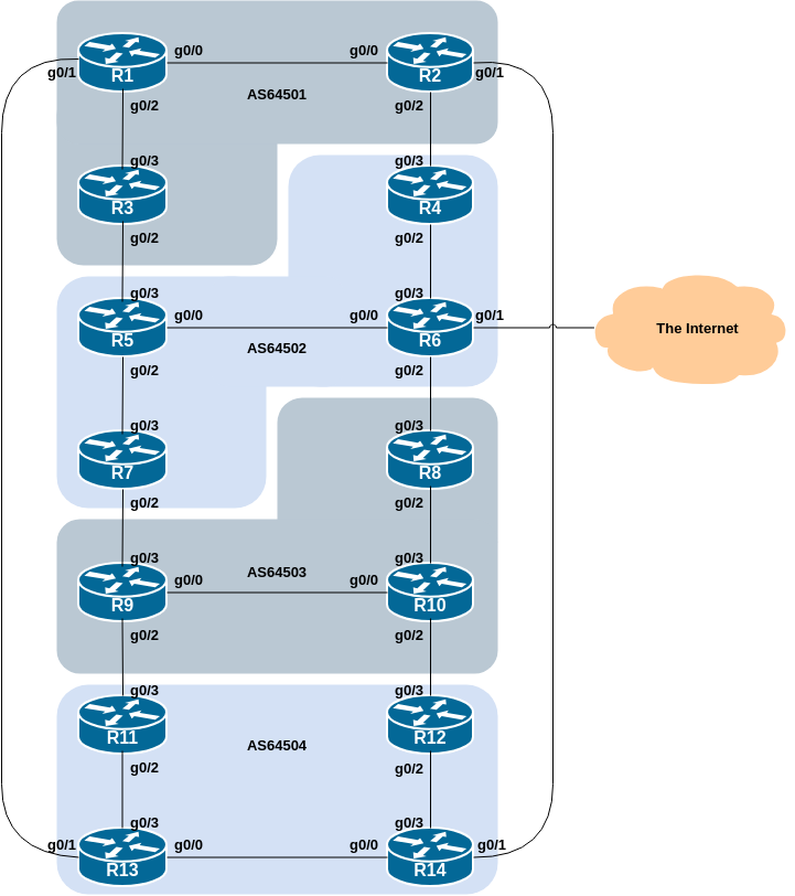
The following common topology is used for this lab.
Before we proceed with this lab we need to tidy up from the Route Filtering lab exercise so that the configurations we are testing here will not be interfered with by what we did before. (And it is also best operational practice to remove all redundant/unused configuration.)
The clean up involves removing all the filtering and community configurations examined in the previous lab.
Here is a list of what needs to be done:
router bgp 6450X
 address-family ipv4
  no neighbor <v4-ebgp-peer> route-map AS6450Y-in in
  no network 100.68.X.0 mask 255.255.255.0 route-map community-tag
  network 100.68.X.0 mask 255.255.255.0
!
 address-family ipv6
  no neighbor <v6-ebgp-peer> route-map AS6450Y-in in
  no network 2001:DB8:X::/48 route-map community-tag
  network 2001:DB8:X::/48
!
no route-map community-tag
no route-map AS6450Y-in
no ip community-list standard AS6450Y
!
Adapt the configuration to suit the EBGP configuration for your router, noting that Router2 and Router9 will have two EBGP peers. X is your group number, Y is your neighbouring group your router has the EBGP session with.
Once you have removed the route policy configuration as per above, remember to do a route-refresh inbound on your EBGP peering.
Retain the send-community configuration added to IBGP and EBGP peers as we will need this again in this lab.
The aim of this series of labs is to demonstrate how to achieve a particular traffic flow using four different methods. These four methods involve applying policies for the modification of outbound traffic flow, and three ways of applying policies to modify inbound traffic flow. The reader should review the BGP presentation given prior to this module as a reminder on how to influence path choice using BGP policies.
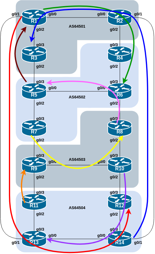
The diagram below displays the desired traffic flows between particular routers and ASes for each of the four methods being investigated. Eight traffic flows are to be implemented.
The arrows in the diagram show the flows that will be configured. Each arrow originates from a border router in an AS, and terminates on one of the routers in another AS. This signifies the traffic flows desired for the links between the two routers.
Each of the policy labs we are going to do has a description on how to implement the traffic flow represented by each arrow. It is important to pause and think what the policy is, and what needs to be done to achieve it.
If at any time there is any doubt as to the configuration required, ask the lab instructors.
The diagram may look “busy” but the key to success is to focus on the traffic engineering that your group needs to do, and “ignore” the other activities by other groups.
To make the different policies in this module work, we will use the customer prefixes we assigned to each router in the previous lab. This way we will be able to target our traffic engineering based on what individual routers announce to the rest of the lab network. This is similar to the real life scenario where an ISP needs to do traffic engineering to meet particular operational requirements.
The addressing used for this lab is documented in the address plan and is replicated here for convenience:
| AS Number | Router | IPv4 subnet | IPv6 subnet |
|---|---|---|---|
| AS64501 | Router1 | 100.68.1.32/28 | 2001:DB8:1:100::/56 |
| Router2 | 100.68.1.48/28 | 2001:DB8:1:200::/56 | |
| Router3 | 100.68.1.64/28 | 2001:DB8:1:300::/56 | |
| AS64502 | Router4 | 100.68.2.32/28 | 2001:DB8:2:100::/56 |
| Router5 | 100.68.2.48/28 | 2001:DB8:2:200::/56 | |
| Router6 | 100.68.2.64/28 | 2001:DB8:2:300::/56 | |
| Router7 | 100.68.2.80/28 | 2001:DB8:2:400::/56 | |
| AS64503 | Router8 | 100.68.3.32/28 | 2001:DB8:3:100::/56 |
| Router9 | 100.68.3.48/28 | 2001:DB8:3:200::/56 | |
| Router10 | 100.68.3.64/28 | 2001:DB8:3:300::/56 | |
| AS64504 | Router11 | 100.68.4.32/28 | 2001:DB8:4:100::/56 |
| Router12 | 100.68.4.48/28 | 2001:DB8:4:200::/56 | |
| Router13 | 100.68.4.64/28 | 2001:DB8:4:300::/56 | |
| Router14 | 100.68.4.80/28 | 2001:DB8:4:400::56 |
As we will be doing traceroutes through the network to check that the policies have worked, we also need to configure another loopback interface with one address out of the IPv4 /28 and IPv6 /56 address blocks. Recall that we routed the block to the Null0 interface in lieu of having a real customer router to connect to. Setting up another Loopback as an IPv4 /32 and IPv6 /128 will serve our purpose well.
Here is a configuration example, as might be used on Router8:
interface Loopback1
 description Routing Policy Target Address
 ip address 100.68.3.32 255.255.255.255
 ipv6 address 2001:DB8:3:100::0/128
!
Modify this configuration to suit the router you are configuring.
The covering aggregates for these two host addresses are already originated by IBGP, configuration we added in the previous lab.
Once you have created the new Loopback interface and assigned the addresses, ask your colleagues in your AS to try ping the loopback interface that you just created (both IPv4 and IPv6 addresses).
This lab demonstrates how to influence outbound traffic flows for each AS. Recall from the presentation that we use local preference to influence outbound traffic flow for our network - its the only direct policy tool that we have available.
Local preference is applied to inbound routing announcements. The address blocks defined in the previous step are used as the target: they are matched on the EBGP peerings and local preference is set high. While we set local preference high on the preferred outbound path, it is important that backup paths should still function – for that reason, we also set local preference low on the other exits from the AS.
The following itemised lists show the primary paths/routing that we want to achieve:
AS 64501:
All traffic TO 100.68.2.64/28 and 2001:DB8:2:300::/56 (Router6) must exit AS 64501 via the link from Router2 to Router4 only.
All traffic TO 100.68.4.48/28 and 2001:DB8:4:200::/56 (Router12) must exit AS 64501 via the link from Router1 to Router13 only.
AS 64502:
All traffic TO 100.68.1.32/28 and 2001:DB8:1:100::/56 (Router1) must exit AS 64502 via the link from Router5 to Router3 only.
All traffic TO 100.68.3.32/28 and 2001:DB8:3:100::/56 (Router8) must exit AS 64502 via the link from Router7 to Router9 only.
AS 64503:
All traffic TO 100.68.2.48/28 and 2001:DB8:2:200::/56 (Router5) must exit AS 64503 via the link from Router8 to Router6 only.
All traffic TO 100.68.4.64/28 and 2001:DB8:4:300::/56 (Router13) must exit AS 64503 via the link from Router10 to Router12 only.
AS 64504:
All traffic TO 100.68.1.64/28 and 2001:DB8:1:300::/56 (Router3) must exit AS 64504 via the link from Router14 to Router2 only.
All traffic TO 100.68.3.48/28 and 2001:DB8:3:200::/56 (Router9) must exit AS 64504 via the link from Router11 to Router9 only.
Note that we are only trying to define outgoing traffic flow. The return path has no policies implemented, and the router’s normal path decision process applies.
The traffic flow we want to achieve above is also visually described in the earlier lab diagram, where the coloured arrows show the traffic flow we want to achieve between ASes. This type of more sophisticated policy and traffic flow is quite common in today’s Internet, as network operators strive to optimise their customers’ experiences.
The example configurations below should be used as guidance for the router configuration for each router team.
For each AS, one router AS will have to set high local-preference on routes learned on their EBGP peering, and the remaining routers will set low local-preference on their EBGP peerings. The motivation for doing this is redundancy of configuration. If, for example, Router7 lost its local-preference configuration due to some operator error, the low local-preference set on the other three routers will ensure that the traffic policies required will still be implemented. It’s quite common for many network operators to have more than one configuration to implement a particular policy – a primary configuration, and an “inverse” secondary configuration on other routers which could be impacted.
Given there are two scenarios for each AS, each router in the AS will have to:
create prefix-lists to match the destination prefixes, one list for each address-family.
create route-maps to implement the policy covering both scenarios.
Note that only one route-map can be used per EBGP session and that we name the route-map in such a way that it is very obvious to the reader of the configuration what the route-map is intended to do.
The example below shows what Router7’s IPv4 configuration could look like to implement the policy described for AS64502 for its peering with Router9:
ip prefix-list R1-v4prefix permit 100.68.1.32/28
ip prefix-list R8-v4prefix permit 100.68.3.32/28
!
route-map R9-v4localpref permit 10
 match ip address prefix-list R1-v4prefix
 set local-preference 50
!
route-map R9-v4localpref permit 20
 match ip address prefix-list R8-v4prefix
 set local-preference 200
!
route-map R9-v4localpref permit 30
!
router bgp 64502
 address-family ipv4
  neighbor 100.68.3.0 remote-as 64503
  neighbor 100.68.3.0 route-map R9-v4localpref in
!
and this is what Router7’s IPv6 configuration could look like:
ipv6 prefix-list R1-v6prefix permit 2001:DB8:1:100::/56
ipv6 prefix-list R8-v6prefix permit 2001:DB8:3:100::/56
!
route-map R9-v6localpref permit 10
 match ipv6 address prefix-list R1-v6prefix
 set local-preference 50
!
route-map R9-v6localpref permit 20
 match ipv6 address prefix-list R8-v6prefix
 set local-preference 200
!
route-map R9-v6localpref permit 30
!
router bgp 64502
 address-family ipv6
  neighbor 2001:DB8:3:1:: remote-as 64503
  neighbor 2001:DB8:3:1:: route-map R9-v6localpref in
!
Let us emphasise again how we have used descriptive names for the prefix-lists and route-maps. It is very clear, reading the configuration examples above, what each prefix-list and each route-map is aiming to do.
As the instructors explained in the BGP Policy presentation, descriptive names for components of the BGP policy language, whichever vendor implementation is used, makes understanding and troubleshooting a configuration all the more straightforward1.
Use the above example to come up with a configuration for your router and the policy it needs to implement on its EBGP session. Discuss with the other members of your group (your AS) - it is likely that you will have some common configuration snippets you can share with each other.
Note: Router2 and Router9 have two EBGP peers, and will need a separate route-map for each peering. Use the hint above, naming the route-map after the peer name (and is also common practice in day to day network operations).
Once the policy has been implemented, remember to run a route-refresh on the EBGP session. And then try doing a traceroute (trace command, and remember to specify the source interface – why?) through the network, to the destination you have targeted. Does the traceroute follow the arrows in the diagram? If not, why not? Maybe check the BGP table and if your colleagues in your AS have completed their steps in the exercise as well.
On completion of the exercise the instructor will display traceroutes to the selected destinations on the classroom screen - the traffic has to exit the AS as specified in the exercise above and the instructor will check from various points of the lab that the traffic is flowing as intended.
Route-maps and prefix-lists can also have description lines included, and that it is recommended that this is done in day to day network operations.↩︎