The purpose of this exercise is to learn how to configure BGP between the Border and Core routers.
In the last routing lab we configured IS-IS between the Border and Core routers. The introduction of BGP allows simpler announcement of address space of the local autonomous network, and allows future possibility of the local network connecting to two different network operators (for example a commercial ISP and the REN).
Make sure to take the examples and adapt them to your own router, network topology and addressing scheme.
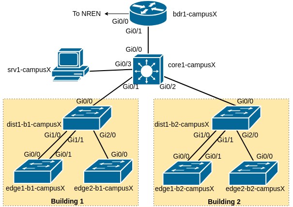
As a reminder, the following diagram shows the layout of the devices and all the links for each campus:
Our campus network consists of two routers, bdr1-campusX and core1-campusX as well as six switches.
The following table shows the connections between each device in the campus:
| Device | Interface | Remote Device | Remote Interface |
|---|---|---|---|
| dist1-bY-campusX | GigabitEthernet1/0 | edge1-bY-campusX | GigabitEthernet0/0 |
| GigabitEthernet1/1 | edge1-bY-campusX | GigabitEthernet0/1 | |
| GigabitEthernet2/0 | edge2-bY-campusX | GigabitEthernet0/0 | |
| core1-campusX | GigabitEthernet0/0 | bdr1-campusX | GigabitEthernet0/1 |
| GigabitEthernet0/1 | dist1-b1-campusX | GigabitEthernet0/0 | |
| GigabitEthernet0/2 | dist1-b2-campusX | GigabitEthernet0/0 | |
| GigabitEthernet0/3 | srv1-campusX | ens3 | |
| bdr1-campusX | GigabitEthernet0/0 | transit1-nren | GigabitEthernet0/X |
| GigabitEthernet0/2 | transit2-nren | GigabitEthernet0/X |
Replace Y with your building number and X with your campus number.
During all exercises, verify the output of the following commands:
show ip bgp sum                : show status of the IPv4 BGP peering
show bgp ipv6 unicast sum      : show status of the IPv6 BGP peering
show ip bgp                    : show the IPv4 BGP table
show bgp ipv6 unicast          : show the IPv6 BGP table
We will now configure a new BGP routing process for both IPv4 and IPv6. As with OSPF, BGP automatically creates the router-id it needs from the IPv4 address configured on the Loopback interface. However, we will bypass this automatic process and instead manually configure the router-id but still using the IPv4 address on the Loopback interface.
On the Core router:
router bgp X0
 no bgp default ipv4-unicast
 bgp deterministic-med
 bgp router-id 100.68.X.242
!
 address-family ipv4
  neighbor 100.68.X.241 remote-as X0
  neighbor 100.68.X.241 update-source loopback 0
  neighbor 100.68.X.241 description iBGP with Border Router
  network 100.68.X.0 mask 255.255.255.0
  distance bgp 200 200 200
!
 address-family ipv6
  neighbor 2001:DB8:X:2::241 remote-as X0
  neighbor 2001:DB8:X:2::241 update-source loopback0
  neighbor 2001:DB8:X:2::241 description iBGP with Border Router
  network 2001:DB8:X::/48
  distance bgp 200 200 200
!
ip route 100.68.X.0 255.255.255.0 Null0
ip route 10.0.0.0 255.0.0.0 Null0
ipv6 route 2001:DB8:X::/48 Null0
Here is an explanation of each command used above - some were not mentioned in the presentation.
bgp default ipv4-unicast means that IOS BGP must not assume that all neighbours will exchange IPv4 prefixes. IPv6 neighbours do not normally exchange IPv4 prefixes!
bgp deterministic-med is a best practice which fixes BGP’s path selection in the instance there are multiple paths with multiple MEDs to the same destination
distance bgp 200 200 200 means that we will set eBGP’s administrative distance to be the same as that of iBGP - another best practice to avoid accidents.
On the Border router:
router bgp X0
 no bgp default ipv4-unicast
 bgp deterministic-med
 bgp router-id 100.68.X.241
!
 address-family ipv4
  neighbor 100.68.X.242 remote-as X0
  neighbor 100.68.X.242 update-source loopback 0
  neighbor 100.68.X.242 description iBGP with Core Router
  network 100.68.X.0 mask 255.255.255.0
  distance bgp 200 200 200
!
 address-family ipv6
  neighbor 2001:DB8:X:2::242 remote-as X0
  neighbor 2001:DB8:X:2::242 update-source loopback0
  neighbor 2001:DB8:X:2::242 description iBGP with Core Router
  network 2001:DB8:X::/48
  distance bgp 200 200 200
!
STOP - Checkpoint.
show ip bgp summary      : show neighbours
show ip route            : show routes in routing table
show ip bgp              : shows general BGP information
The status commands for IPv6 are very similar: simply replace ip bgp in the above show commands with bgp ipv6.
Question: How many routes do you see in BGP for both IPv4 and IPv6?
The final task for this lab is to set up BGP between the Border router and the NREN router. To do this we are setting up eBGP on the border router, peering on the point to point link address of the link to the NREN.
As was mentioned in the presentation, BGP is very chatty. In the absence of any filters, it will send all prefixes on the router, and will accept all prefixes it hears from a neighbour. Before we connect any BGP speaking router to the public Internet we must prepare filters for it.
ip prefix-list NREN-in permit 0.0.0.0/0
!
ip prefix-list CampusX-out permit 100.68.X.0/24
!
ipv6 prefix-list NREN-v6in permit ::/0
!
ipv6 prefix-list CampusX-v6out permit 2001:DB8:X::/48
These filters in order, do the following:
Only allow IPv4 default route in from the NREN
Only allow the Campus public IPv4 address block out to the NREN
Only allow IPv6 default route in from the NREN
Only allow the Campus IPv6 address block out to the NREN
Now the filters are prepared we can set up BGP with the NREN. Here is a configuration example for the Border router - modify this example to suit your Campus. The instructors will have already configured BGP on the NREN router to talk to the campus border router.
router bgp X0
!
 address-family ipv4
  neighbor 100.68.0.N remote-as 65534
  neighbor 100.68.0.N description eBGP with NREN
  neighbor 100.68.0.N prefix-list NREN-in in
  neighbor 100.68.0.N prefix-list CampusX-out out
!
 address-family ipv6
  neighbor 2001:DB8:0:X:: remote-as 65534
  neighbor 2001:DB8:0:X:: description eBGP with NREN
  neighbor 2001:DB8:0:X:: prefix-list NREN-v6in in
  neighbor 2001:DB8:0:X:: prefix-list CampusX-v6out out
!
Have you established BGP sessions with the NREN? (IPv4 and IPv6)
Check the BGP table. Do you see the default route learned from the NREN?
If you do, now is a good time to remove the static default currently pointing to the NREN - we set this up in an earlier exercise.
no ip route 0.0.0.0 0.0.0.0 100.68.0.N
no ipv6 route ::/0 2001:db8:0:X::
Now look at the BGP table again. Do you see any difference from previously?
Also, if you now look at the Routing Table and compare with the BGP table, what do you also notice.
Here is an example from a previous Campus Network Design & Operations Workshop. How does this BGP table and Routing table compare with the entries you see?
Routing table:
bdr1-campus2>sh ip route
Codes: L - local, C - connected, S - static, R - RIP, M - mobile, B - BGP
       D - EIGRP, EX - EIGRP external, O - OSPF, IA - OSPF inter area
       N1 - OSPF NSSA external type 1, N2 - OSPF NSSA external type 2
       E1 - OSPF external type 1, E2 - OSPF external type 2
       i - IS-IS, su - IS-IS summary, L1 - IS-IS level-1, L2 - IS-IS level-2
       ia - IS-IS inter area, * - candidate default, U - per-user static route
       o - ODR, P - periodic downloaded static route, H - NHRP, l - LISP
       a - application route
       + - replicated route, % - next hop override, p - overrides from PfR

Gateway of last resort is 100.68.0.5 to network 0.0.0.0

B*    0.0.0.0/0 [200/0] via 100.68.0.5, 00:04:23
      10.0.0.0/8 is variably subnetted, 7 subnets, 3 masks
S        10.0.0.0/8 is directly connected, Null0
i L2     10.1.0.0/24 [115/2] via 100.68.2.2, 00:05:27, GigabitEthernet0/1
i L2     10.1.1.0/24 [115/2] via 100.68.2.2, 00:05:27, GigabitEthernet0/1
i L2     10.1.8.0/21 [115/2] via 100.68.2.2, 00:05:27, GigabitEthernet0/1
i L2     10.2.0.0/24 [115/2] via 100.68.2.2, 00:05:27, GigabitEthernet0/1
i L2     10.2.1.0/24 [115/2] via 100.68.2.2, 00:05:27, GigabitEthernet0/1
i L2     10.2.8.0/21 [115/2] via 100.68.2.2, 00:05:27, GigabitEthernet0/1
      100.0.0.0/8 is variably subnetted, 10 subnets, 4 masks
C        100.68.0.4/30 is directly connected, GigabitEthernet0/0
L        100.68.0.6/32 is directly connected, GigabitEthernet0/0
S        100.68.2.0/24 is directly connected, Null0
C        100.68.2.0/28 is directly connected, GigabitEthernet0/1
L        100.68.2.1/32 is directly connected, GigabitEthernet0/1
i L2     100.68.2.128/28 [115/2] via 100.68.2.2, 00:05:27, GigabitEthernet0/1
C        100.68.2.241/32 is directly connected, Loopback0
i L2     100.68.2.242/32 [115/2] via 100.68.2.2, 00:05:27, GigabitEthernet0/1
and BGP table:
bdr1-campus2>sh ip bgp
BGP table version is 3, local router ID is 100.68.2.241
Status codes: s suppressed, d damped, h history, * valid, > best, i - internal,
              r RIB-failure, S Stale, m multipath, b backup-path, f RT-Filter,
              x best-external, a additional-path, c RIB-compressed,
              t secondary path,
Origin codes: i - IGP, e - EGP, ? - incomplete
RPKI validation codes: V valid, I invalid, N Not found

     Network          Next Hop            Metric LocPrf Weight Path
 *>  0.0.0.0          100.68.0.5               0             0 65534 i
 * i 100.68.2.0/24    100.68.2.242             0    100      0 i
 *>                   0.0.0.0                  0         32768 i
If time allows, you can try multi-homing to the second NREN transit router.
The second link connects to port GigabitEthernet0/2 on the border router, and the link addresses are numbered as follows:
| Campus | NREN Link Subnet | NREN Router Address | Campus Border Router Address |
|---|---|---|---|
| 1 | 100.68.0.128/30 | 100.68.0.129 | 100.68.0.130 |
| 2 | 100.68.0.132/30 | 100.68.0.133 | 100.68.0.134 |
| 3 | 100.68.0.136/30 | 100.68.0.137 | 100.68.0.138 |
| 4 | 100.68.0.140/30 | 100.68.0.141 | 100.68.0.142 |
| 5 | 100.68.0.144/30 | 100.68.0.145 | 100.68.0.146 |
| 6 | 100.68.0.148/30 | 100.68.0.149 | 100.68.0.150 |
And for IPv6:
| Campus | NREN Link Subnet | NREN Router Address | Campus Border Router Address |
|---|---|---|---|
| 1 | 2001:DB8:100:33::/127 | 2001:DB8:100:33::0 | 2001:DB8:100:33::1 |
| 2 | 2001:DB8:100:34::/127 | 2001:DB8:100:34::0 | 2001:DB8:100:34::1 |
| 3 | 2001:DB8:100:35::/127 | 2001:DB8:100:35::0 | 2001:DB8:100:35::1 |
| 4 | 2001:DB8:100:36::/127 | 2001:DB8:100:36::0 | 2001:DB8:100:36::1 |
| 5 | 2001:DB8:100:37::/127 | 2001:DB8:100:37::0 | 2001:DB8:100:37::1 |
| 6 | 2001:DB8:100:38::/127 | 2001:DB8:100:38::0 | 2001:DB8:100:38::1 |
You will need to:
Configure the link addresses, and check you can ping the transit2-nren router
Bring up additional eBGP peering sessions to the transit-nren2 router
Try shutting down GigabitEthernet0/0, and check that traffic fails over to the other link