The purpose of this exercise is to learn how to configure OSPF between the Border and Core routers so that they exchange network reachability information and maintain their own routing tables dynamically.
In an earlier lab we configured some static routes to forward packets between the Border and Core routers. While it’s possible to run the network like this it can be difficult to keep the static routes up to date as your network changes. It won’t be possible to use static routes if dual core and dual border routers are deployed (how to do this is a topic for a future lab).
Make sure to take the examples and adapt them to your own router, network topology and addressing scheme.
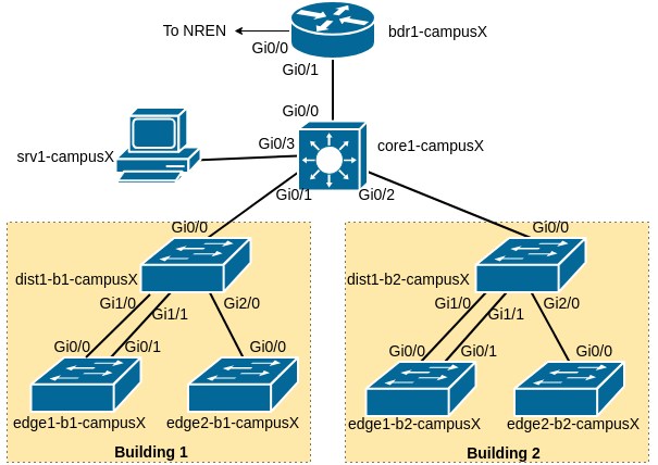
As a reminder, the following diagram shows the layout of the devices and all the links for each campus:
Our campus network consists of two routers, bdr1-campusX and core1-campusX as well as six switches.
During the exercises, you may find these commands useful to verify:
show arp                 : Shows ARP cache
show interface <int>     : Shows interface state and configuration
show ip interface        : Shows interface IPv4 state and configuration
show ipv6 interface      : Shows interface IPv6 state and configuration
show run interface <int> : Shows the configuration of the interface
We will now prepare the border and core router to introduce OSPF to them. We will be replacing the static routes we configured earlier with OSPF, where the routes on each router are announced to their neighbour. In future this will mean that we do not need to introduce a static route when we introduce new subnets in our campus.
First of all we will set up a Loopback interface on both routers. It is industry convention and best practice to create a Loopback interface on all L3 devices, for various reasons. Remember to change X to your group number.
On the Border router:
interface Loopback0
 ip address 100.68.X.241 255.255.255.255
 ipv6 address 2001:DB8:X:2::241/128
On the Core router:
interface Loopback0
 ip address 100.68.X.242 255.255.255.255
ipv6 address 2001:DB8:X:2::242/128We now start the OSPF routing processes: OSPFv2 for IPv4, and OSPFv3 for IPv6.
On the Border router: (As usual, change X to your group number)
router ospf 41
 router-id 100.68.X.241
 log-adjacency-changes detail
 passive-interface default
!
router ospfv3 41
 router-id 100.68.X.241
 log-adjacency-changes detail
 address-family ipv6
  passive-interface default
On the Core router:
router ospf 41
 router-id 100.68.X.242
 log-adjacency-changes detail
 passive-interface default
!
router ospfv3 41
 router-id 100.68.X.242
 log-adjacency-changes detail
 address-family ipv6
  passive-interface default
Note: “41” is a process identifier. It can be any number you want, and is entirely internal to the router. Some operators use their AS number here.
Both OSPFv2 and OSPFv3 require a unique 32-bit router ID. It is conventional to use the router’s IPv4 loopback address for this.
In OSPF, a “passive” interface is one where we do not send any HELLO messages. It is best practice to set this as the default for all interfaces, so that we only send HELLO messages on the specific interfaces we enable.
As we will be using neighbour authentication as discussed in the OSPF presentation, next we create the authentication key-chain. “ospf-key” is a label for the key, and “cndlab123” is the actual secret value.
! Do this on both BORDER and CORE
key chain ospf-key
 key 1
   key-string cndlab123
cryptographic-algorithm hmac-sha-512The authentication is added in to the OSPF processes. For OSPFv2 we’ll later have to apply the key chain to each interface; for OSPFv3 we can set it globally.
! Do this on both BORDER and CORE
router ospf 41
 area 0 authentication message-digest
!
router ospfv3 41
area 0 authentication key-chain ospf-keyWe need to announce the IPv4 and IPv6 Loopback interface addresses to other OSPF speakers. This is done by enabling “ip ospf” and “ipv6 ospf” on the interface. (Note: it does not actually send HELLO packets on this interface, since it’s still a “passive” interface)
! Do this on both BORDER and CORE
interface Loopback0
 ip ospf 41 area 0
ipv6 ospf 41 area 0We will now enable OSPF on the interfaces where adjacencies need to be established. We activate both IPv4 and IPv6 adjacencies.
Note that each ethernet interface is declared to be point-to-point - even though they are broadcast interfaces, there are only two devices so we do not need the Designated Router election as with normal broadcast media.
We also have to disable “passive-interface” to enable sending HELLOs on those interfaces.
On the Border router:
interface GigabitEthernet0/1
 ip ospf 41 area 0
 ip ospf network point-to-point
 ip ospf authentication key-chain ospf-key
 ipv6 ospf 41 area 0
 ipv6 ospf network point-to-point
!
router ospf 41
 no passive-interface GigabitEthernet0/1
!
router ospfv3 41
 address-family ipv6
  no passive-interface GigabitEthernet0/1
On the Core router:
interface GigabitEthernet0/0
 ip ospf 41 area 0
 ip ospf network point-to-point
 ip ospf authentication key-chain ospf-key
 ipv6 ospf 41 area 0
 ipv6 ospf network point-to-point
!
router ospf 41
 no passive-interface GigabitEthernet0/0
!
router ospfv3 41
 address-family ipv6
  no passive-interface GigabitEthernet0/0
STOP - Checkpoint.
show ip ospf             : shows general OSPF information
show ip ospf neighbor    : show adjacencies
show ip route            : show all routes in main RIB
show ip route ospf       : show only OSPF routes
show ip ospf rib         : shows the OSPF Routing Information Base (RIB)
show ip ospf interface   : shows the status of OSPF in an interface
The status commands for IPv6 are very similar: simply replace “ip” in the above show commands with “ipv6”.
Do the border and core routers see each other as neighbors?
Has each router learned a route to the loopback address of the other?
Question: When you run show ip ospf rib on the Border router, do you see the subnets for the VLANs downstream of the Core router, e.g. the Wired and Wireless VLANs and the Server network?
Answer: You won’t see these yet. You need to tell the Core router to announce those subnets in OSPF. You do this by enabling “ip ospf…” and “ipv6 ospf…” on each interface, whilst still leaving them as “passive-interface” so it doesn’t send any OSPF packets on those interfaces.
On the Core:
interface GigabitEthernet0/3
 ip ospf 41 area 0
 ipv6 ospf 41 area 0
interface Vlan10
 ip ospf 41 area 0
 ipv6 ospf 41 area 0
interface Vlan11
 ip ospf 41 area 0
 ipv6 ospf 41 area 0
interface Vlan18
 ip ospf 41 area 0
 ipv6 ospf 41 area 0
interface Vlan20
 ip ospf 41 area 0
 ipv6 ospf 41 area 0
interface Vlan21
 ip ospf 41 area 0
 ipv6 ospf 41 area 0
interface Vlan28
 ip ospf 41 area 0
 ipv6 ospf 41 area 0
Now you should see them on the border.
We now will use OSPF to announce a default route into the core network. This will replace the static default route currently in use. To do this, we use the following commands.
On the border router:
router ospf 41
 default-information originate
!
router ospfv3 41
 address-family ipv6
  default-information originate
This will originate a default route into OSPF (which means that it will be distributed to OSPF neighbours) as long as a default route exists in the router’s Global RIB. The default is already in the Border Router Global RIB because of the static default route we set up in the Static Routing Lab exercise.
Check the OSPF RIB on the Core Router to make sure you see the default there. On the Core Router, do:
show ip ospf rib
show ipv6 ospf rib
You should see the default route for IPv4 (0.0.0.0/0) and IPv6 (::/0) in the OSPF RIB using the above commands.
Once the Border router is announcing the default route by OSPF, you can remove the static default route on the Core router using:
no ip route 0.0.0.0 0.0.0.0 100.68.X.1
no ipv6 route ::/0 2001:DB8:X::1
Check that routing to the other groups is still working using:
show ip route
show ipv6 route
You should see the default route in the table as an OSPF external type 2 (O E2) announcement. There should now be no static routes remaining in the core router, apart from the Null0 (pull-up) routes.
The OSPF Lab is normally conducted after completing the static routing exercise. There are static routes for the internal address space on the Border router to reach the internal network.
We will now remove the static routes, carefully. The routes are now learned by OSPF from the Core router. Here is the configuration example:
! On the BORDER router
no ip route 100.68.X.0 255.255.255.0 100.68.X.2
no ip route 10.0.0.0 255.0.0.0 100.68.X.2
no ipv6 route 2001:DB8:X::/48 2001:DB8:X:0::2
To finish off, all teams should now check the Routing Table. Document the output of:
show ip route
show ipv6 route
and be prepared to show this to the workshop instructors. The group network is now using a dynamic routing protocol to share routing information within the group - a much more scalable solution than the effort that was required to set up the static routes in the previous lab exercise.
As with the previous static routing lab, because we now learn all internal specific routes via OSPF, we can add the Null routes for the covering aggregates onto the Border as well:
! On the BORDER router
ip route 100.68.X.0 255.255.255.0 Null0
ip route 10.0.0.0 255.0.0.0 Null0
ipv6 route 2001:DB8:X::/48 Null0
Check the routing table you see on both the border and core routers now. Do you have full Internet connectivity for IPv4 - check by trying to ping or traceroute to 8.8.8.8. If you have followed the steps above you’d have migrated your campus from static routes to dynamic routing using OSPF without any break in connectivity.
Here is an example of the routing table from the Border router in campus1 from a previous Campus Network Design Workshop:
bdr1-campus1#sh ip route
Codes: L - local, C - connected, S - static, R - RIP, M - mobile, B - BGP
       D - EIGRP, EX - EIGRP external, O - OSPF, IA - OSPF inter area
       N1 - OSPF NSSA external type 1, N2 - OSPF NSSA external type 2
       E1 - OSPF external type 1, E2 - OSPF external type 2
       i - IS-IS, su - IS-IS summary, L1 - IS-IS level-1, L2 - IS-IS level-2
       ia - IS-IS inter area, * - candidate default, U - per-user static route
       o - ODR, P - periodic downloaded static route, H - NHRP, l - LISP
       a - application route
       + - replicated route, % - next hop override, p - overrides from PfR

Gateway of last resort is 100.68.0.1 to network 0.0.0.0

S*    0.0.0.0/0 [1/0] via 100.68.0.1
      10.0.0.0/8 is variably subnetted, 7 subnets, 3 masks
S        10.0.0.0/8 is directly connected, Null0
O        10.1.0.0/24 [110/2] via 100.68.1.2, 00:08:57, GigabitEthernet0/1
O        10.1.1.0/24 [110/2] via 100.68.1.2, 00:03:53, GigabitEthernet0/1
O        10.1.8.0/21 [110/2] via 100.68.1.2, 00:03:53, GigabitEthernet0/1
O        10.2.0.0/24 [110/2] via 100.68.1.2, 00:08:57, GigabitEthernet0/1
O        10.2.1.0/24 [110/2] via 100.68.1.2, 00:03:53, GigabitEthernet0/1
O        10.2.8.0/21 [110/2] via 100.68.1.2, 00:03:53, GigabitEthernet0/1
      100.0.0.0/8 is variably subnetted, 8 subnets, 4 masks
C        100.68.0.0/30 is directly connected, GigabitEthernet0/0
L        100.68.0.2/32 is directly connected, GigabitEthernet0/0
S        100.68.1.0/24 is directly connected, Null0
C        100.68.1.0/28 is directly connected, GigabitEthernet0/1
L        100.68.1.1/32 is directly connected, GigabitEthernet0/1
O        100.68.1.128/28 [110/2] via 100.68.1.2, 00:08:57, GigabitEthernet0/1
C        100.68.1.241/32 is directly connected, Loopback0
O        100.68.1.242/32 [110/2] via 100.68.1.2, 00:08:57, GigabitEthernet0/1
How well does this compare with what you see?
What about IPv6?