The purpose of this lab is to now add Layer 3 functionality to our newly finished Layer 2 network. The Core Switch has basic L3 capability right now in that it is routing between the different VLANs configured on it. However, we now want to give the campus connectivity to the border router and onwards to the NREN and the Internet.
The class will continue in its groups with each group being assigned one campus to configure; attention will now be turned to configuring routing on the border router and core router (which we have been calling a switch up to now).
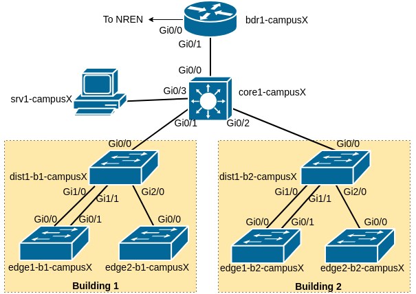
The following diagram shows the layout of the devices and all the links for each campus:
Our campus network consists of two routers, bdr1-campusX and core1-campusX as well as six switches. We have already configured the distribution and edge switches, as well as completed the L2 configuration of the core router. We will not need to touch any of the L2 configuration any more.
As we saw when we set up the switches earlier on in the workshop, we have to apply basic initial configuration to our Border Router as well, before we configure any IP addresses or any routing on it. The following is what you need to do, exactly the same initial configuration you applied to the switches.
Before going to the static routing lab, apply the following configuration to the Border Router. If you don’t remember what some of the configuration does, please refer back to the L2 Setup Lab for a detailed explanation.
Note that more modern versions of Cisco’s IOS will use type 9 (scrypt) encryption for the username and enable secrets. Also note that for a persistent ifindex, the SNMP command used for a router is slightly different from what we used on the switches.
It’s up to you to go into configuration mode (conf t) and leave configuration mode (end) when required.
! Remember to change "X" in hostname and username below
hostname bdr1-campusX
!
service timestamps debug datetime msec localtime show-timezone year
service timestamps log datetime msec localtime show-timezone year
!
aaa new-model
aaa authentication login default local
aaa authentication enable default enable
!
username campusX algorithm-type scrypt secret lab-PW
enable algorithm-type scrypt secret lab-EN
service password-encryption
!
no ip domain lookup
ip domain name ws.nsrc.org
!
no logging console
logging buffered 8192 debug
!
ip ssh version 2
crypto key generate rsa modulus 2048
!
snmp-server group ReadGroup v3 auth
snmp-server user admin ReadGroup v3 auth sha NetManage
snmp-server location Campus Network Design Workshop
snmp-server ifindex persist
!
banner login ^
Campus Network Design and Operations Workshop Lab
         Network Startup Resource Center
^
!
line con 0
 transport preferred none
 escape-character 3
 exec-timeout 30 0
!
line aux 0
 transport preferred none
 escape-character 3
 exec-timeout 30 0
!
line vty 0 4
 transport preferred none
 transport input ssh
 escape-character 3
 exec-timeout 30 0
Once you have applied the above template, remember to save the configuration using write mem.
The full address plan for the lab can be found in the IP Address Plan. Consult the address plan for the addresses of the point to point links between the Campus Border Router and the NREN Router.
Make sure you change the X and N below to the correct value from address plan mentioned above:
! This is on the BORDER
interface GigabitEthernet0/0
 description Link to NREN
 ip address 100.68.0.N 255.255.255.252
 ipv6 address 2001:DB8:100:X::1/127
 no ip redirects
 no ip proxy-arp
 load-interval 30
 ipv6 nd prefix default no-advertise
 ipv6 nd ra suppress all
 no shutdown
Leave configuration mode, then test that you can ping the NREN end of the link:
ping 100.68.0.M           !! where M is the far end (the NREN router's address)
ping 2001:DB8:100:X::
If this doesn’t work, STOP and fix it before continuing. Ask for help if needed.
What happens if you try to communicate with an address outside your campus, such as an IP inside the NREN? Try these commands:
ping 100.68.0.251
ping 2001:db8:100:ff::251
Is there no answer?
Look at the IPv4 Routing Information Base:
bdr1-campus1#show ip route
Codes: L - local, C - connected, S - static, R - RIP, M - mobile, B - BGP
       D - EIGRP, EX - EIGRP external, O - OSPF, IA - OSPF inter area
       N1 - OSPF NSSA external type 1, N2 - OSPF NSSA external type 2
       E1 - OSPF external type 1, E2 - OSPF external type 2
       i - IS-IS, su - IS-IS summary, L1 - IS-IS level-1, L2 - IS-IS level-2
       ia - IS-IS inter area, * - candidate default, U - per-user static route
       o - ODR, P - periodic downloaded static route, H - NHRP, l - LISP
       a - application route
       + - replicated route, % - next hop override, p - overrides from PfR

Gateway of last resort is not set

      100.0.0.0/8 is variably subnetted, 4 subnets, 3 masks
C        100.68.0.0/30 is directly connected, GigabitEthernet0/0
L        100.68.0.2/32 is directly connected, GigabitEthernet0/0
The router knows about the local (L) and connected (C) networks but not any other network. In particular, there is no prefix which includes the address 100.68.0.251.
What about IPv6? (Use show ipv6 route). What routes do you see for IPv6 destinations? Is there a similarity with what you see for IPv4?
SOLUTION: the Border router needs a default route added to it so that it can forward traffic to destinations on the wider Internet via the NREN. We add this route to send traffic to the NREN router:
! On the BORDER
ip route 0.0.0.0 0.0.0.0 100.68.0.M       !! The address of the NREN router
ipv6 route ::/0 2001:DB8:100:X::0
Choose the correct values for X and M from the IP address tables we used when we set up the interface.
Once this is done, check you can ping outside:
ping 100.68.0.251
ping 2001:db8:100:ff::251
If these don’t work, STOP and check your work so far.
You can also test external addresses on the Internet, like Google DNS:
ping 8.8.8.8
ping 2001:4860:4860::8888    !! this will only work if the classroom has IPv6 connectivity
Now that the Border is working, the next step is to bring connectivity to the Core.
Still on the border router, you need to configure the interface that links towards the core.
Make sure you change the X below to the correct value for your campus:
! This is on the BORDER
interface GigabitEthernet0/1
 description Link to Core
 ip address 100.68.X.1 255.255.255.240
 ipv6 address 2001:DB8:X:0::1/64
 no ip redirects
 no ip proxy-arp
 load-interval 30
 ipv6 nd prefix default no-advertise
 ipv6 nd ra suppress all
 no shutdown
We will now configure the interface on the Core Router connecting it to the Border Router. Since we will never carry multiple VLANs on this link, we can configure the port as a pure layer 3 (routed) interface, using the no switchport command.
Make sure you change the X below to the correct value for your campus:
! This is on the CORE
interface GigabitEthernet0/0
 description Link to Border
 no switchport
 ip address 100.68.X.2 255.255.255.240
 ipv6 address 2001:DB8:X:0::2/64
 no ip redirects
 no ip proxy-arp
 load-interval 30
 ipv6 nd prefix default no-advertise
 ipv6 nd ra suppress all
 no shutdown
Test that you can ping your Border router at the other end this link.
! On the CORE
ping 100.68.X.1
ping 2001:DB8:X:0::1
If this doesn’t work, STOP and fix it. You may need to check the interface configuration on the border router.
From the core router, what happens if you try to communicate with an address outside your campus, such as inside the NREN? Try these commands:
! Run these on the CORE
ping 100.68.0.251
ping 2001:db8:100:ff::251
Let’s look at the routing information on the Core router:
core1-campus1#show ip route
Codes: L - local, C - connected, S - static, R - RIP, M - mobile, B - BGP
       D - EIGRP, EX - EIGRP external, O - OSPF, IA - OSPF inter area
       N1 - OSPF NSSA external type 1, N2 - OSPF NSSA external type 2
       E1 - OSPF external type 1, E2 - OSPF external type 2
       i - IS-IS, su - IS-IS summary, L1 - IS-IS level-1, L2 - IS-IS level-2
       ia - IS-IS inter area, * - candidate default, U - per-user static route
       o - ODR, P - periodic downloaded static route, H - NHRP, l - LISP
       a - application route
       + - replicated route, % - next hop override, p - overrides from PfR

Gateway of last resort is not set

      10.0.0.0/8 is variably subnetted, 12 subnets, 2 masks
C        10.1.0.0/24 is directly connected, Vlan10
L        10.1.0.1/32 is directly connected, Vlan10
C        10.2.0.0/24 is directly connected, Vlan20
L        10.2.0.1/32 is directly connected, Vlan20
      100.0.0.0/8 is variably subnetted, 4 subnets, 2 masks
C        100.68.1.0/28 is directly connected, GigabitEthernet0/0
L        100.68.1.2/32 is directly connected, GigabitEthernet0/0
(And show ipv6 route for IPv6)
Just as we found on the border, there is no route a prefix which includes 100.68.0.251.
SOLUTION: the Core router needs a default route added so that it can forward traffic from the Campus network to the wider Internet. We add this route to send traffic to the border router:
! On the CORE
ip route 0.0.0.0 0.0.0.0 100.68.X.1
ipv6 route ::/0 2001:DB8:X:0::1
Once this is done, try pinging outside again:
ping 100.68.0.251
ping 2001:db8:100:ff::251
Do you find that IPv4 works, but IPv6 doesn’t?
Cisco IOS routers have IPv6 Routing turned off by default. So while we can reach our directly attached neighbours, we cannot get anywhere beyond, nor can we turn on any IPv6 routing protocols. We now need to turn on IPv6 routing, and to do that we use the following two commands:
! Do these commands on both the BORDER and CORE routers
ipv6 unicast-routing
ipv6 cef
(IPv4 routing is of course already on by default. At some point in the future Cisco may well turn on IPv6 routing by default.)
Once this is done, try pinging outside from the core router again:
! On the CORE router
ping 100.68.0.251
ping 2001:db8:100:ff::251

traceroute 100.68.0.251
traceroute 2001:db8:100:ff::251
If these don’t work, STOP and check your work so far.
You can also test external addresses, like Google DNS:
ping 8.8.8.8
ping 2001:4860:4860::8888    !! this will only work if the classroom has IPv6 connectivity
The core itself can now reach the Internet, but it also needs to provide service to subnets downstream from it.
Our network management and monitoring server, srv1-campusX.ws.nsrc.org, is connected to GigabitEthernet0/3 on the core router. We’ll configure the router, core1-campusX, so that we can start to use that server to manage and monitor our network. Again, since we are only routing a single subnet on this interface, we can configure the port as a routed interface using the no switchport command:
! On the CORE
interface GigabitEthernet0/3
 description Network Management and Monitoring
 no switchport
 ip address 100.68.X.129 255.255.255.240
 ipv6 address 2001:DB8:X:1::1/64
 no ip redirects
 no ip proxy-arp
 load-interval 30
 ipv6 nd prefix default no-advertise
 ipv6 nd ra suppress all
 no shutdown
Now connect to the console port of srv1 in your campus. Login as the “sysadm” user, with the password given to you by the workshop instructors.
From srv1, you should be able to ping the core router using the addresses you’ve just added to its GigabitEthernet0/3 interface:
! Do this on srv1 at the Linux shell prompt
ping 100.68.X.129
ping6 2001:DB8:X:1::1
Use Ctrl-C to stop the pings.
Now what about pinging outside?
! Do this on srv1
ping 100.68.0.251
traceroute -n -w1 100.68.0.251
Oh dear, something is wrong. srv1 has already been configured with an IP address and a default gateway pointing at the core. You can check it like this:
! Do this on srv1
ip route
ip -6 route
Also, traceroute shows the packets reaching the first hop. But if srv1 already has a default gateway, why can’t it ping outside?
The problem this time is more subtle. For ping to work, we need communication in both directions: the “echo request” needs to arrive at the target, but the target also needs to be able to send an “echo response” back to us.
Try doing a traceroute to srv1 from the border router:
! Do this on the BORDER
traceroute 100.68.X.130
The border has no route to the server network, so instead the traffic follows the default gateway. The NREN knows that the 100.68.X block belongs inside the campus, so sends it back again. There’s an infinite loop.
We could add a route on the border just for the server network, pointing at the core. But there are many other subnets which we need to reach via the core as well; without a dynamic routing protocol like OSPF or IS-IS, we would have to add them all one by one.
The simplest solution is to route all the campus address space - public IPv4, private IPv4 and IPv6 - to the core.
! Do this on the BORDER
ip route 100.68.X.0 255.255.255.0 100.68.X.2
ip route 10.0.0.0 255.0.0.0 100.68.X.2
ipv6 route 2001:DB8:X::/48 2001:DB8:X:0::2
Now the border says “any campus IP address goes to the core; anything else goes to the NREN”. Remember that the most specific route (longest prefix) wins.
Go back to the srv1 command line, and test again:
! Do this on srv1
ping 100.68.0.251
ping6 2001:db8:100:ff::251

traceroute -n -w1 100.68.0.251
traceroute6 -n -w1 2001:db8:100:ff::251
Is it working now, on both IPv4 and IPv6? If not, check your work or ask for help.
On the core router, you already added IP addresses on vlan 10 and vlan 20 (switch management subnets), but it also needs to provide service on the WIRED and WIFI VLANs. Here is an example for VLAN 11, the WIRED VLAN in Building 1:
! Do this on the CORE router
interface vlan 11
 description Wired VLAN of Building 1
 ip address 10.1.1.1 255.255.255.0
 ipv6 address 2001:DB8:X:11::1/64
 load-interval 30
 no shutdown
Replace X with your campus number. Do the same for all the other VLANs as well.
Once completed, your Core switch should have VLANs 11, 18, 21 and 28 configured with both IPv4 and IPv6 addresses.
Question: What is significant about the IP address configured on each VLAN?
Answer: This IP address now serves as the default gateway for every device connecting to this VLAN. So a user on VLAN 11 will have default gateway 10.1.1.1, etc.
NB: This configuration only goes on the core switch, not the distribution and access switches.
The switches also need a default route added to them so that their NETMGMT VLAN can forward traffic to elsewhere in the network - without it, management traffic will only ever be able to reach other devices on their own VLAN.
On each switch, we add this default route to forward traffic to the Core router. (Note that this doesn’t affect how the switch carries user traffic; it’s only for when the switch itself wants to send management traffic from its own IP)
For Building 1 try:
! On the DIST and EDGE switches in building 1
ip route 0.0.0.0 0.0.0.0 10.1.0.1
ipv6 route ::/0 2001:DB8:X:10::1
For Building 2 try:
! On the DIST and EDGE switches in building 2
ip route 0.0.0.0 0.0.0.0 10.2.0.1
ipv6 route ::/0 2001:DB8:X:20::1
Now test it. First ping out to the border router:
! Try from any dist or edge switch
ping 100.68.X.1
ping 2001:DB8:X:0::1
These should both work. If they don’t, there’s a problem that needs fixing.
Then test to the NREN:
! Try from the same dist or edge switch
ping 100.68.0.251
ping 2001:db8:100:ff::251
Do you find that IPv4 doesn’t work, but IPv6 does work?
The reason is that the dist and edge switches are using private IP addresses for their management IPs. We would have to configure NAT on the border router to make this work.
We are only using some of the subnets in our network address allocation. If we receive packets from outside our network to these ranges:
100.68.X.0/24
10.0.0.0/8
2001:DB8:X::/48
we need to discard the packet unless we have a route for the appropriate subnet. For example, what should we do with a packet addressed to 100.68.X.67?
On the Core router try running the show ip route command - you should see something like in the example below:
core1-campusX#show ip route 100.68.X.67
% Subnet not in table
core1-campusX#traceroute 100.68.X.67
Type escape sequence to abort.
Tracing the route to 100.68.X.67
VRF info: (vrf in name/id, vrf out name/id)
  1 100.68.X.1 1 msec 1 msec 1 msec
  2 100.68.X.2 0 msec 0 msec 1 msec
  3 100.68.X.1 1 msec 1 msec 1 msec
  4 100.68.X.2 1 msec 1 msec 0 msec
  5 100.68.X.1 2 msec 1 msec 1 msec
  6 100.68.X.2 1 msec 1 msec 1 msec
...
The only entry in the routing table that matches this address is the default route1.
Also, what do we do with a packet addressed to 10.2.55.128 that might have come from one of the campus devices connected to the Access switches? This is part of the 10.0.0.0/8 address block we use for the internal campus network, but we don’t have a routing table entry for it, apart from the default route. Here is an example from the Core router of Campus 1:
core1-campus1#show ip route 10.2.55.128
% Subnet not in table
and then:
core1-campus1#show ip route 0.0.0.0
Routing entry for 0.0.0.0/0, supernet
  Known via "static", distance 1, metric 0, candidate default path
  Routing Descriptor Blocks:
  * 100.68.1.1
      Route metric is 0, traffic share count is 1
You’ll note that the specific destination is not in the Core router’s routing table; but we have a static default route, and so traffic to 10.2.55.128 will be sent to the Border router which will then send it back to the Core router.
It’s good practice to have routes in place that drop traffic like this. We do this on the Core router only using:
! On the CORE
ip route 100.68.X.0 255.255.255.0 Null0
ip route 10.0.0.0 255.0.0.0 Null0
ipv6 route 2001:DB8:X::/48 Null0
The more specific connected routes on the Core router are still able to deliver traffic (because longest prefix wins), but anything else is caught by the Null routes and thrown away.
And because we are now sending traffic destined for unannounced routes towards the Null interface, we need to set up the Null interface to not respond with ICMP unreachable messages for IPv4 and IPv6 (this is so that a stream of traffic to unannounced routes does not result in the router sending “unreachable” responses).
Add the following on both the Core and Border routers:
interface Null0
 no ip unreachables
 no ipv6 unreachables
Finally, go back to your srv1 system and try this snmpstatus command. If it is not installed on the srv1 system, you’ll need to install it:
sudo apt install snmpThen you can run:
snmpstatus -v3 -l authNoPriv -u admin -a SHA -A NetManage x.x.x.xreplacing x.x.x.x with the IP address of the management interface of one of the campus devices. What do you see?
You should see something like the following:
[UDP: [10.x.y.z]:161->[0.0.0.0]:35559]=>[Cisco IOS Software, vios_l2 Software (vios_l2-ADVENTERPRISEK9-M), Experimental Version 15.2(20200924:215240) [sweickge-sep24-2020-l2iol-release 135]
Copyright (c) 1986-2020 by Cisco Systems, Inc.
Compiled Tue 29-Sep-20 11:53 by sweickge] Up: 0:16:14.95
Interfaces: 0, Recv/Trans packets: 11058/10597 | IP: 3/2
Try with all your campus devices.
This output shows that the response from one of the campus devices - and is another way of confirming that both the routing from your srv1 system to the management interfaces of the campus devices is working, and that the SNMP configuration you installed on each campus device during the setup of the workshop lab is actually working too!
Call an instructor and show them your working system. Show them the traceroutes from your core router and server system (srv1) out to the Internet.
From your srv1, you can try using SSH to connect to the router’s command line over the network:
# Do this on srv1 at the Linux shell prompt
ssh campusX@100.68.X.129
If this works, enter the router password to log in; then log out again. We are doing this just to verify connectivity; we will come back and make use of the network management and monitoring server later on in the workshop.
Many routers and switches older versions of SSH crypto, which are disabled in newer versions of OpenSSH. When you SSH to one of these devices from a modern Linux server, you might see an error like this:
Unable to negotiate with 100.68.X.129 port 22: no matching key exchange method found.
Their offer: diffie-hellman-group-exchange-sha1,diffie-hellman-group14-sha1,diffie-hellman-group1-sha1
This means the router only supports old cryptography algorithms which are disabled in newer versions of the SSH client (“sha1” is an insecure hash algorithm).
To fix this, create a new config file with an editor of your choice - we suggest using “nano” which is simple to use.
sudo nano /etc/ssh/ssh_config.d/cisco.confInsert the following content (changing ‘X’ as appropriate):
Host 100.68.X.129
  KexAlgorithms +diffie-hellman-group-exchange-sha1,diffie-hellman-group14-sha1
  HostKeyAlgorithms +ssh-rsa
  PubkeyAcceptedAlgorithms +ssh-rsa
  # Very old devices may also need this:
  Ciphers +aes256-cbc,3des-cbc
This configures the client to permit these older algorithms when talking to this device.
Then exit and save. (For nano: hit ctrl-X, then press “y” to confirm the save, then hit Enter to confirm the filename). Finally, try making the ssh connection again.
If your ssh connection hangs, and ctrl-C doesn’t break out, then use the SSH escape sequence (tilde ~ followed by a dot .) to disconnect. Then you can investigate what might have gone wrong.
Because the only matching destination is the default route pointing to the Border router, the Core router will send any packets for 100.68.1.67 to the default route, the Border router. The Border router sees the destination is part of the Campus address block, so sends the packets to the Core router. And the cycle repeats, a looping packet consumes bandwidth and router CPU until the time to live expires. Best practice is to drop such traffic with a Null route.↩︎