
This module rebuilds the workshop network so that we can simulate four different interconnected ISP backbones using a combination of IS-IS, internal BGP, and external BGP.
The pre-requisites for this lab is that the IBGP lab has been completed and the instructors have presented the BGP Attributes presentation.
The purpose of this module is to introduce the student to external BGP (EBGP). This is the relationship between different autonomous systems in an “Internet”. The classroom has been split into four distinct networks, and the teams belonging to each network work together as a typical ISP. Each AS has two links to its neighbouring ASes, and this feature will used throughout a significant portion of this workshop.
The following common topology is used for the remainder of the labs.
The table below shows the membership of each AS. As noted in the Introduction, the teams operating each of the routers in an AS work together to ensure the success of the lab:
| AS Number | Members |
|---|---|
| 64501 | Router1, Router2, and Router3 |
| 64502 | Router4, Router5, Router6, and Router7 |
| 64503 | Router8, Router9, and Router10 |
| 64504 | Router11, Router12, Router13, and Router14 |
The instructors will have reset the entire configuration of each router before starting this lab.
Each router team will now rebuild the configuration from scratch, using the first 14 steps of the setup lab, and then continuing from the next step below.
If you did not save the configuration from the previous modules, you will need to go back and look up the notes for the setup lab.
As a reminder, the steps you need to carry out are:
Name the router
Disable DNS resolution
Set the domain name
Configure the Console, Auxiliary, and VTY access
Configure Users & Passwords
Configure Authentication
Configure Logging
Activate IPv6 Routing
Disable Source Routing
Turn off the Built-in Web Server
Enable Path MTU discovery
Set up a login banner
Set up SecureShell
Save the Configuration!
Once you have completed these steps, you will be ready to move on to the next section. Ask the instructor to verify your configuration if you are not sure you have completed them.
As previously we need to come up with a sensible and scalable addressing plan for each AS in this network.
Each AS gets their own address block for IPv4 and for IPv6. This address block is used for the links and loopbacks on the routers making up each AS. The allocations are as follows:
| Group | AS Number | IPv4 Address Block | IPv6 Address Block |
|---|---|---|---|
| 1 | 64501 | 100.68.1.0/24 | 2001:DB8:1::/48 |
| 2 | 64502 | 100.68.2.0/24 | 2001:DB8:2::/48 |
| 3 | 64503 | 100.68.3.0/24 | 2001:DB8:3::/48 |
| 4 | 64504 | 100.68.4.0/24 | 2001:DB8:4::/48 |
and are also documented in the Address Plan document.
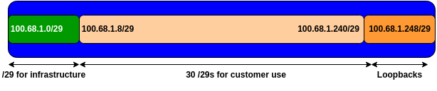
We have subdivided the IPv4 /24 very cautiously, using /31s for point-to-point links out of a /29 at the start of the range, and a /29 for Loopbacks at the end of the range.
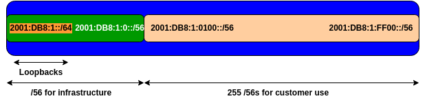
We have subdivided the IPv6 address /48 so that we have a /56 for our infrastructure (including a /64 for loopbacks), and the 255 remaining /56s we could distribute out to our customers. This diagram shows what we have done:
As with the previous exercises, we need to divide up each address block so that we have customer address space, network infrastructure address space, and some space for loopbacks.
The address plan for the entire network is described in the Address Plan document.
Each router team should now assign IPv4 and IPv6 addresses, as per the address plan, to each active interface on their router. Once complete, each team should ping the adjacent neighbour to make sure that connectivity works over both IPv4 and IPv6.
Hint: Don’t forget about the Null0 interface and don’t forget about the Loopback0 interface either!
As we saw in the earlier lab with a single AS, the classroom network has a transit link, available from Router6. The group operating Router6 will now have to enable this transit connectivity.
The transit link is on interface GigabitEthernet 0/1 of Router6. Here is the additional configuration required:
interface GigabitEthernet0/1
 description Link to the World
 ip address 100.64.0.254 255.255.252.0
 ipv6 address FE80::254 link-local
 ipv6 address 2001:DB8::254/64
!
Once the interface is configured, test that it works by pinging 100.64.0.1 and FE80::1 which are IPv4 and IPv6 default gateways respectively.
Here is an example from earlier for IPv4:
Router6#ping 100.64.0.1
Type escape sequence to abort.
Sending 5, 100-byte ICMP Echos to 100.64.0.1, timeout is 2 seconds:
!!!!!
Success rate is 100 percent (5/5), round-trip min/avg/max = 1/1/1 ms
Router6#
And for IPv6:
Router6#ping fe80::1 source GigabitEthernet0/1
Output Interface: GigabitEthernet0/1
Type escape sequence to abort.
Sending 5, 100-byte ICMP Echos to FE80::1, timeout is 2 seconds:
Packet sent with a source address of FE80::254%GigabitEthernet0/1
!!!!!
Success rate is 100 percent (5/5), round-trip min/avg/max = 1/1/1 ms
Router6#
If the ping is successful we can now add in default routes for IPv4 and IPv6:
ip route 0.0.0.0 0.0.0.0 100.64.0.1
ipv6 route ::/0 GigabitEthernet0/1 FE80::1
Note that the default route for IPv6 needs to include the interface - the link-local address is local to the link, so we need to specify which link to use!
Test the IPv4 and IPv6 connectivity using traceroute to Google’s public DNS resolver (8.8.8.8 and 2001:4860:4860::8888) as we did earlier in the workshop.
This section configures the IS-IS routing protocol. If any of the steps are unclear, refer back to the earlier IS-IS lab for more detailed information.
In each AS configure IS-IS routing. This means that each router team should configure router isis with IS-IS ID asY on the router, where Y is the AS number assigned to the group.
And the internal links to each member of the AS must be configured with ip router isis asY and ipv6 router isis asY.
The NET should be 49.0001.group#.router#.00; refer to the previous IS-IS lab for more details on how we construct the NET. For example, the loopback for Router6 (the 3rd router in Group 2) is 2001:DB8:2::3 which will make the NSAP address 49.0001.0002.0003.00.
We still require neighbour authentication for IS-IS. This time we’ll make the key used specific to our Group - replace the X with your Group number:
key chain isis-key
 key 1
  key-string groupX
!
Here is a possible configuration (replacing X with Group number and Y with the final character of the Router’s IPv6 loopback address):
router isis as6450X
 net 49.0001.000X.000Y.00
 authentication mode md5 level-2
 authentication key-chain isis-key level-2
 is-type level-2-only
 metric-style wide
 metric 100000
 log-adjacency-changes
 set-overload-bit on-startup wait-for-bgp
!
 address-family ipv6
  multi-topology
  metric 100000
  set-overload-bit on-startup wait-for-bgp
!
IS-IS must be configured on internal interfaces only. You do not want to set up adjacencies with devices outside your AS. Make sure that there are no ip router isis commands on external interfaces. A side effect of this is that external link addresses will not appear in the IGP (see the next section discussing IBGP deployment).
As an example, Router1 has two interfaces inside AS64501, and would have the following configuration:
interface GigabitEthernet0/0
 description Link to Router2
 isis network point-to-point
 ip router isis as64501
 ipv6 router isis as64501
 isis metric 2
 isis ipv6 metric 2
!
interface GigabitEthernet0/2
 description Link to Router3
 isis network point-to-point
 ip router isis as64501
 ipv6 router isis as64501
 isis metric 2
 isis ipv6 metric 2
!
Now mark the interfaces on which you do not want to run IS-IS as passive. For IS-IS, marking an interface as passive means that CLNS adjacencies are not solicited and the IP subnet used on the interface is inserted into IS-IS.
For this lab we are only going to mark the Loopback interface as passive. Note that you cannot mark interfaces as passive until you have IS-IS assigned to at least one physical interface on the router (as you did in the previous step).
Here is a configuration example (replacing X with your Group number):
router isis as6450X
 passive-interface Loopback0
!
Router6 has the transit link to the outside world. So that other routers in AS64502 can also access the outside world, Router6 team now has to distribute this default route to the rest of our AS and to the rest of the lab.
To distribute to the other routers in AS64502, Router6 needs to configure the following in their IS-IS set up:
router isis as64502
 default-information originate
!
 address-family ipv6
  default-information originate
!
Once the configuration has been added, Router4, Router5 and Router7 should have a default route for both IPv4 and IPv6, pointing to Router6. Those teams in AS64502 should now try a traceroute to Google’s public DNS resolver, as was done earlier.
Important Note: this configuration unconditionally originates the default route. In the operational world, network operators would usually announce the default conditionally, that is, if the default route is in the router’s Global RIB, then it would be distributed by IS-IS as well.
Check the routes which are available via IS-IS. Make sure you can see all the networks within your AS, and see no networks from other ASs. Ping all loopback interfaces within your AS. Use the show clns neighbor, show isis neigbor, show ip route, and show ipv6 route commands.
If you find adjacencies with routers outside your AS, discuss this with the team operating the other router, and resolve the problem.
Most ISPs use the router Loopback address for administrative purposes as well as the anchor point for their network’s IBGP sessions. In this step we will configure SecureShell (SSH) so that it uses the loopback interface as the source address for all SSH packets originated by the router:
ip ssh source-interface Loopback0To check that this has worked, use ssh from your router to a neighbouring router and then enter the who command. You will see that you are logged in, and the source address will be displayed.
(We can do the same for telnet too - we’ve disabled telnet as our incoming transport, but it is still active for outgoing - this can be useful for troubleshooting connectivity to remote TCP ports.)
The next phase of this lab is to configure IBGP peering between routers within an AS. Each AS has either 3 or 4 routers in it.
As we learned before, it is rare for a network operator to implement a full mesh IBGP today, due to scalability issues. So for this lab we will again use Route Reflectors.
And as we did in the previous lab, we will also use Peer Groups for configuring our IBGP sessions.
We will make one router the Route Server, and the other routers in the AS will be the Clients.
Here are the assignments we will use:
| Group | Route Reflector | Clients |
|---|---|---|
| 1 | Router1 | Router2 & Router3 |
| 2 | Router 6 | Router4, Router5, Router7 |
| 3 | Router10 | Router8 & Router9 |
| 4 | Router13 | Router11, Router12, Router14 |
And the following diagram shows the IBGP sessions (in red) between the Route Reflectors and the Clients in each AS.
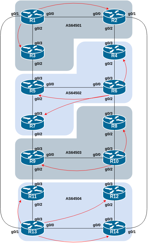
Each group should now configure IBGP within their AS. The Route Reflector will have IBGP sessions with the Clients, and each Client will only have an IBGP session with their Route Reflector.
Remember to set up the basic IBGP configuration on every router in the AS as per the earlier IBGP lab (replacing X with your Group number):
router bgp 6450X
 bgp log-neighbor-changes
 bgp deterministic-med
 no bgp default ipv4-unicast
!
 address-family ipv4
  distance bgp 200 200 200
!
 address-family ipv6
  distance bgp 200 200 200
!
We’ll also set a password on the BGP sessions - this time we will use a password related to our Group number: groupX-PW where we replace X with our Group number.
The following steps apply to the Route Reflectors in each AS - we selected Router1, Router6, Router10 and Router13 earlier.
Remember from the previous IBGP lab that we originated the address block of the AS from the Route Reflector itself. Refer back to that lab on how to set up a Route Reflector for the AS.
First we originate the IPv4 and IPv6 aggregates from the Route Reflector:
router bgp 6450X
 address-family ipv4
  network 100.68.X.0 mask 255.255.255.0
!
 address-family ipv6
  network 2001:DB8:X::/48
!
ip route 100.68.X.0 255.255.255.0 Null0
ipv6 route 2001:DB8:X::/48 Null0
!
Next we create the Route Reflector Client Peer Group (remember to replace X with your Group number):
router bgp 6450X
 address-family ipv4
  neighbor rr-v4client peer-group
  neighbor rr-v4client remote-as 6450X
  neighbor rr-v4client update-source Loopback0
  neighbor rr-v4client next-hop-self
  neighbor rr-v4client description IBGP with Client
  neighbor rr-v4client route-reflector-client
  neighbor rr-v4client password groupX-PW
!
 address-family ipv6
  neighbor rr-v6client peer-group
  neighbor rr-v6client remote-as 6450X
  neighbor rr-v6client update-source Loopback0
  neighbor rr-v6client next-hop-self
  neighbor rr-v6client description IBGP with Client
  neighbor rr-v6client route-reflector-client
  neighbor rr-v6client password groupX-PW
!
And then we set up the IBGP sessions with the Clients.
Here is an example of what the Route Reflector configuration might look like for a Route Reflector with one Client:
router bgp 6450X
 address-family ipv4
  neighbor 100.68.X.251 peer-group rr-v4client
  neighbor 100.68.X.251 description IBGP with Client
  neighbor 100.68.X.251 activate
!
 address-family ipv6
  neighbor 2001:DB8:X::1 peer-group rr-v6client
  neighbor 2001:DB8:X::1 description IGP with Client
  neighbor 2001:DB8:X::1 activate
!
Use the above example to help you design the configuration you need for your Route Reflector’s BGP sessions with the clients in your AS.
The clients only have an IBGP session with the Route Reflector. Again refer back to the previous IBGP lab on what configuration is required.
First we create the Client’s Peer Group used for the peering with the Route Reflector:
router bgp 6450X
 address-family ipv4
  neighbor rr-v4 peer-group
  neighbor rr-v4 remote-as 6450X
  neighbor rr-v4 update-source Loopback0
  neighbor rr-v4 next-hop-self
  neighbor rr-v4 description IBGP with Route Reflector
  neighbor rr-v4 password groupX-PW
!
 address-family ipv6
  neighbor rr-v6 peer-group
  neighbor rr-v6 remote-as 6450X
  neighbor rr-v6 update-source Loopback0
  neighbor rr-v6 next-hop-self
  neighbor rr-v6 description IBGP with Route Reflector
  neighbor rr-v6 password groupX-PW
!
Here is an example of what the Route Reflector Client configuration might look like, talking to its Route Reflector:
router bgp 6450X
 address-family ipv4
  neighbor 100.68.X.253 peer-group rr-v4
  neighbor 100.68.X.253 description IBGP with RouterN
  neighbor 100.68.X.253 activate
!
 address-family ipv6
  neighbor 2001:DB8:X::3 peer-group rr-v6
  neighbor 2001:DB8:X::3 description IBGP with RouterN
  neighbor 2001:DB8:X::3 activate
!
Use the above example to help you design the configuration you need for your Route Reflector Client’s BGP session with its Route Reflector in your AS.
Once the Route Reflector and its Clients have been set up in each Group, each Group should verify that the IBGP sessions are working (for both IPv4 and IPv6) and that the aggregates are visible.
The final stage of this lab is to configure External BGP between each AS. Use the diagram at the start of these notes to determine the links between the ASes.
Addressing for EBGP links between 2 ASes will use the point-to-point interface addresses, NOT the loopback addresses (review the BGP presentation if you don’t understand why).
This example shows what the EBGP configuration between Router1 and Router13 might look like:
router bgp 64501
 address-family ipv4
  neighbor 100.68.1.7 remote-as 64504
  neighbor 100.68.1.7 description EBGP with Router13
  neighbor 100.68.1.7 password BGP-PW
  neighbor 100.68.1.7 activate
!
 address-family ipv6
  neighbor 2001:DB8:1:4::1 remote-as 64504
  neighbor 2001:DB8:1:4::1 description EBGP with Router13
  neighbor 2001:DB8:1:4::1 password BGP-PW
  neighbor 2001:DB8:1:4::1 activate
!
Discuss with the EBGP neighbour what password to use on the EBGP session - the passwords have to match!
Use the above configuration example to establish the EBGP session with your neighbour AS. Note that Router2 and Router9 have two EBGP peers.
We haven’t used Peer Groups for our EBGP sessions - it is possible to do so, but really only makes sense when you have multiple EBGP peers sharing the same configuration (typically at an Internet Exchange Point).
Question: Why can’t the loopback interfaces be used for the EBGP peerings?
Answer: The IP address of a router’s loopback interface is not known to external BGP peers, so the external peers will have no way of knowing how to contact each other to establish the peering.
Question: Which BGP show command allows you to see the state of the BGP connection to your peer?
Answer: Try show ip bgp neighbor x.x.x.x and show bgp ipv6 unicast neighbour x:x:x::x – this will give detailed information about the state of the peer for IPv4 and IPv6 respectively. There are subcommands of this one, giving more information about the peering.
Question: Which BGP Show command will allow you to see exactly which networks you are advertising and receiving from your EBGP peers?
Answer: Try show ip bgp neighbor x.x.x.x route and show bgp ipv6 unicast neighbor x:x:x::x – this will show which routes you are receiving from your peer. Likewise, replacing route with advertised-routes will list the networks which are being announced to your peer. (Note that in general ISP operational practice, there are caveats here – if you apply route-maps and some BGP policies, these will not be processed by the advertised-routes command. Use the advertised-routes subcommand with due caution.)
To distribute the default route to other routers in the lab network (outside AS64502 that is), Router6 needs to add the default route into BGP. We will use a somewhat unconventional way of doing this, as follows:
router bgp 64502
 address-family ipv4
  network 0.0.0.0
!
 address-family ipv6
  network ::/0
!
The other ASes should now check that they can see the default route in both IPv4 and IPv6 BGP tables. And if they do, they should test connectivity using traceroute to Google’s public DNS resolver (as above).
Important Note: This is a rather unconventional way of doing things, and it is specific to this lab only. Network operators on the Internet would normally learn the default route by EBGP from their upstream transit provider, and the propagate it either via IS-IS or by IBGP across their network (and onwards by EBGP to their BGP customers). But because we don’t have a BGP speaking upstream for the lab we’ll originate the default route into BGP this way.
Now that Router6 has enabled the external interface connecting the lab to the world, and we have a working traceroute to the outside world, we can turn on DNS name resolution on our routers.
To do this, we tell the router the IP address of the DNS resolver, and enable domain lookups using the Loopback interface IP address as the source address, like this:
ip name-server 100.64.0.1
ip domain lookup source-interface Loopback0
Once this has been done, the router will attempt to use the DNS resolver to look up the name of the device and display that, rather than its IP address. If you try a traceroute to Google’s public resolver, you should see names appearing, rather than the IP addresses.
Note: if in any future lab your router loses connectivity to the classroom resolver (which will happen in some of the scenarios being tested), you should turn off DNS name resolution again by doing:
no ip domain lookupand then traceroutes and other diagnostic commands that use the DNS will not appear to hang.
Question: why are we using the Loopback0 interface as the source for DNS lookups?
Answer: because we do not route the inter-AS point-to-point links in our IS-IS so the other routers in the AS have no visibility of the point-to-point link, and so the connection to the DNS resolver will fail. You will also have noticed this with traceroutes - that they need to be sourced from the Loopback interface in several cases.
As we did in the initial IBGP lab, we are now going to add a “customer” route into BGP on each router. We don’t have any “customers” as such connected to our routers in the lab, so we are going to simulate the connectivity by simply using a Null0 interface. The “customer” address space that each router team will introduce into the IBGP is listed below – we will use an IPv4 /28 and an IPv6 /56.
Consult the Address Plan document to see what the IPv4 and IPv6 address block assignments are for each AS. Once you have determined the address block and which router has to originate which prefix, then set up the necessary configuration.
Each team should now set up a static route pointing to the Null0 interface for the IPv4 /28 and IPv6 /56 that they are to originate. Once the static route is set up, the team should then add an entry into the BGP table. Here is an example for Router8:
ip route 100.68.3.32 255.255.255.240 Null0
ipv6 route 2001:DB8:3:100::/56 Null0
!
router bgp 64503
 address-family ipv4
  network 100.68.3.32 mask 255.255.255.240
!
 address-family ipv6
  network 2001:DB8:3:100::/56
!
Use this example to construct the necessary configuration for your router.
Are there routes visible by show ip bgp and show bgp ipv6 unicast ? If not, why not?
Once every team in the class has done their configuration, each team should see the aggregate from each AS, as well as the fourteen subnets introduced in the previous step. If this is not happening, work with your neighbours to fix the problem.
Here is what the IPv4 table looks like from Router6’s perspective, taken in an earlier version of this workshop:
Router6#show ip bgp
BGP table version is 24, local router ID is 100.68.2.253
Status codes: s suppressed, d damped, h history, * valid, > best, i - internal,
              r RIB-failure, S Stale, m multipath, b backup-path, f RT-Filter,
              x best-external, a additional-path, c RIB-compressed,
              t secondary path,
Origin codes: i - IGP, e - EGP, ? - incomplete
RPKI validation codes: V valid, I invalid, N Not found

     Network          Next Hop            Metric LocPrf Weight Path
 *>   0.0.0.0          100.64.0.1               0         32768 i
 * i  100.68.1.0/24    100.68.2.252             0    100      0 64501 i
 *>i                   100.68.2.251             0    100      0 64501 i
 * i  100.68.1.32/28   100.68.2.252             0    100      0 64501 i
 *>i                   100.68.2.251             0    100      0 64501 i
 * i  100.68.1.48/28   100.68.2.252             0    100      0 64501 i
 *>i                   100.68.2.251             0    100      0 64501 i
 *>i  100.68.1.64/28   100.68.2.251             0    100      0 64501 i
 * i                   100.68.2.252             0    100      0 64501 i
 *>   100.68.2.0/24    0.0.0.0                  0         32768 i
 *>i  100.68.2.32/28   100.68.2.251             0    100      0 i
 *>i  100.68.2.48/28   100.68.2.252             0    100      0 i
 *>   100.68.2.64/28   0.0.0.0                  0         32768 i
 *>i  100.68.2.80/28   100.68.2.254             0    100      0 i
 * i  100.68.3.0/24    100.68.2.254             0    100      0 64503 i
 *>                    100.68.2.9                             0 64503 i
 * i  100.68.3.32/28   100.68.2.254             0    100      0 64503 i
 *>                    100.68.2.9               0             0 64503 i
 *>   100.68.3.48/28   100.68.2.9                             0 64503 i
 * i                   100.68.2.254             0    100      0 64503 i
 * i  100.68.3.64/28   100.68.2.254             0    100      0 64503 i
 *>                    100.68.2.9                             0 64503 i
 * i  100.68.4.0/24    100.68.2.251             0    100      0 64501 64504 i
 * i                   100.68.2.252             0    100      0 64501 64504 i
 *>                    100.68.2.9                             0 64503 64504 i
 * i                   100.68.2.254             0    100      0 64503 64504 i
 * i  100.68.4.32/28   100.68.2.251             0    100      0 64501 64504 i
 * i                   100.68.2.252             0    100      0 64501 64504 i
 *>                    100.68.2.9                             0 64503 64504 i
 * i                   100.68.2.254             0    100      0 64503 64504 i
 * i  100.68.4.48/28   100.68.2.252             0    100      0 64501 64504 i
 * i                   100.68.2.251             0    100      0 64501 64504 i
 * i                   100.68.2.254             0    100      0 64503 64504 i
 *>                    100.68.2.9                             0 64503 64504 i
 * i  100.68.4.64/28   100.68.2.252             0    100      0 64501 64504 i
 * i                   100.68.2.251             0    100      0 64501 64504 i
 * i                   100.68.2.254             0    100      0 64503 64504 i
 *>                    100.68.2.9                             0 64503 64504 i
 * i  100.68.4.80/28   100.68.2.254             0    100      0 64503 64504 i
 *>                    100.68.2.9                             0 64503 64504 i
 * i                   100.68.2.252             0    100      0 64501 64504 i
 * i                   100.68.2.251             0    100      0 64501 64504 i
Are there any observations you’d like to make about the BGP table? For example, why are there 4 paths to the subnets originated by AS64504 (Router11 to Router14)? Discuss. Ask the instructor if you are unsure about what is going on here.
What about IPv6? Here is Router6’s IPv6 BGP table, again from an earlier version of this workshop:
Router6#show bgp ipv6 unicast
BGP table version is 24, local router ID is 100.68.2.253
Status codes: s suppressed, d damped, h history, * valid, > best, i - internal,
              r RIB-failure, S Stale, m multipath, b backup-path, f RT-Filter,
              x best-external, a additional-path, c RIB-compressed,
              t secondary path,
Origin codes: i - IGP, e - EGP, ? - incomplete
RPKI validation codes: V valid, I invalid, N Not found

     Network          Next Hop            Metric LocPrf Weight Path
 *>   ::/0             FE80::1                  0         32768 i
 * i  2001:DB8:1::/48  2001:DB8:2::2            0    100      0 64501 i
 *>i                   2001:DB8:2::1            0    100      0 64501 i
 * i  2001:DB8:1:100::/56
                       2001:DB8:2::2            0    100      0 64501 i
 *>i                   2001:DB8:2::1            0    100      0 64501 i
 * i  2001:DB8:1:200::/56
                       2001:DB8:2::2            0    100      0 64501 i
 *>i                   2001:DB8:2::1            0    100      0 64501 i
 * i  2001:DB8:1:300::/56
                       2001:DB8:2::2            0    100      0 64501 i
 *>i                   2001:DB8:2::1            0    100      0 64501 i
 *>   2001:DB8:2::/48  ::                       0         32768 i
 *>i  2001:DB8:2:100::/56
                       2001:DB8:2::1            0    100      0 i
 *>i  2001:DB8:2:200::/56
                       2001:DB8:2::2            0    100      0 i
 *>   2001:DB8:2:300::/56
                       ::                       0         32768 i
 *>i  2001:DB8:2:400::/56
                       2001:DB8:2::4            0    100      0 i
 * i  2001:DB8:3::/48  2001:DB8:2::4            0    100      0 64503 i
 *>                    2001:DB8:2:5::1                        0 64503 i
 * i  2001:DB8:3:100::/56
                       2001:DB8:2::4            0    100      0 64503 i
 *>                    2001:DB8:2:5::1          0             0 64503 i
 * i  2001:DB8:3:200::/56
                       2001:DB8:2::4            0    100      0 64503 i
 *>                    2001:DB8:2:5::1                        0 64503 i
 * i  2001:DB8:3:300::/56
                       2001:DB8:2::4            0    100      0 64503 i
 *>                    2001:DB8:2:5::1                        0 64503 i
 * i  2001:DB8:4::/48  2001:DB8:2::4            0    100      0 64503 64504 i
 *>                    2001:DB8:2:5::1                        0 64503 64504 i
 * i                   2001:DB8:2::2            0    100      0 64501 64504 i
 * i                   2001:DB8:2::1            0    100      0 64501 64504 i
 * i  2001:DB8:4:100::/56
                       2001:DB8:2::4            0    100      0 64503 64504 i
 *>                    2001:DB8:2:5::1                        0 64503 64504 i
 * i                   2001:DB8:2::2            0    100      0 64501 64504 i
 * i                   2001:DB8:2::1            0    100      0 64501 64504 i
 * i  2001:DB8:4:200::/56
                       2001:DB8:2::4            0    100      0 64503 64504 i
 *>                    2001:DB8:2:5::1                        0 64503 64504 i
 * i                   2001:DB8:2::2            0    100      0 64501 64504 i
 * i                   2001:DB8:2::1            0    100      0 64501 64504 i
 * i  2001:DB8:4:300::/56
                       2001:DB8:2::4            0    100      0 64503 64504 i
 *>                    2001:DB8:2:5::1                        0 64503 64504 i
 * i                   2001:DB8:2::2            0    100      0 64501 64504 i
 * i                   2001:DB8:2::1            0    100      0 64501 64504 i
 * i  2001:DB8:4:400::/56
                       2001:DB8:2::4            0    100      0 64503 64504 i
 *>                    2001:DB8:2:5::1                        0 64503 64504 i
 * i                   2001:DB8:2::2            0    100      0 64501 64504 i
 * i                   2001:DB8:2::1            0    100      0 64501 64504 i
Router6#
Apart from the longer IPv6 address causing a line break1 in the BGP table output, what do you notice about the IPv6 BGP table?
Hopefully the paths to get from Router6 to other subnets around the classroom network are the same as they are for IPv4. If they are not, it might be worth investigating, as this is a likely sign of an EBGP session not working as expected.
Note: more modern versions of IOS support the show bgp all command - this one will display the BGP table for all address families on the router, and is likely preferable (less typing!) to doing the show commands for each address family.
How many origin types exist in BGP?
List the origin types. Hint: Review the BGP presentations.
How are they used?
Why are passwords necessary on both IBGP and EBGP sessions? What do they protect against?
Why is aggregation important for the Internet?
Other BGP implementations which use Cisco IOS syntax (such as FRrouting) have a useful option on the show command called “wide” which expands the BGP table output so that IPv6 addresses fit on the same row as the next hop and other BGP attributes, improving readability.↩